MODERN NETWORKING ARCHITECTURE
The control plane, blast radius, and enforcement decisions that determine what your network actually is — before you configure a single interface.
Enterprise networks are not connectivity systems. They are control plane systems that happen to move packets.
That reframe is not semantic. It is the most consequential shift in how modern networking architecture should be approached — and most enterprise networks are designed without it. The dominant mental model for network architecture starts at Layer 3: routing protocols, VLAN segmentation, firewall rules, load balancer configuration. Those are real concerns. They are also the wrong starting point. The decisions that determine blast radius, failure domain, and the real cost of change happen before any of that configuration is written. They happen at the control plane layer.
The control plane is where routing decisions are made and distributed. It is where policy is defined and enforced. It is where the network’s understanding of itself lives — what paths exist, what is reachable, what is permitted. A network with a misconfigured control plane does not fail loudly. It fails gradually, in ways that accumulate until a change event or failure exposes the divergence between what the control plane believes and what the data plane is actually doing. By the time that divergence is visible, diagnosing it is significantly harder than it would have been at design time.
Modern networking architecture adds three additional variables that the traditional model was not built to handle simultaneously. Software-defined networking centralized the control plane — which simplified day-to-day operations and concentrated blast radius into a single controller failure domain. Cloud-native VPCs moved the control plane to a provider API — which eliminated operational overhead and removed operator visibility and control in equal measure. Kubernetes CNI selection made the network control plane a code-level decision — which tied enforcement boundary, failure domain, and debugging model to a manifest choice that most teams make once and never revisit. Each of these shifts changed where the control plane lives, who owns it, and what happens when it fails. None of them changed the fundamental principle: the network is what the control plane says it is.
This guide introduces the Rack2Cloud Network Plane Model — the framework that maps modern networking architecture against the variables that actually matter for design decisions. It covers physical fabric and SDN, cloud-native VPC architecture, Kubernetes CNI selection, network segmentation as blast radius design, hybrid connectivity as split control plane management, and the IaC discipline that makes network architecture enforceable rather than aspirational. The Network Control Plane Test provides a structured way to determine whether your environment’s control plane is genuinely under your authority — or whether it only appears to be.
The Network Illusion
Enterprise network architecture fails for the same reason enterprise storage architecture fails: the framing that surrounds the design decision is systematically incomplete. Teams design for connectivity. They get connectivity. What they do not always get is the blast radius, the enforcement model, or the control plane authority they believed they were building.
The table below names the five beliefs most responsible for network architecture decisions that look correct at design time and fail under pressure.
| What Teams Think They Built | What They Actually Built |
|---|---|
| Segmented network | Flat network with policy exceptions |
| Highly available routing | Control plane with hidden single points of failure |
| Secure east-west traffic | Implicit trust with partial enforcement |
| Hybrid connectivity | Split control plane with undefined authority |
| Cloud VPC isolation | API-dependent network boundary with opaque failure behavior |
The segmentation row deserves to be named directly: a flat network with policy exceptions is not a segmented network. It is a network where lateral movement requires bypassing access control list rules rather than crossing a genuine isolation boundary. The difference matters when those ACL rules are the only thing between a compromised workload and the rest of the environment. VLAN tags and firewall rules are enforcement mechanisms. They are not the same as blast radius containment — a distinction that surfaces at exactly the worst possible moment.
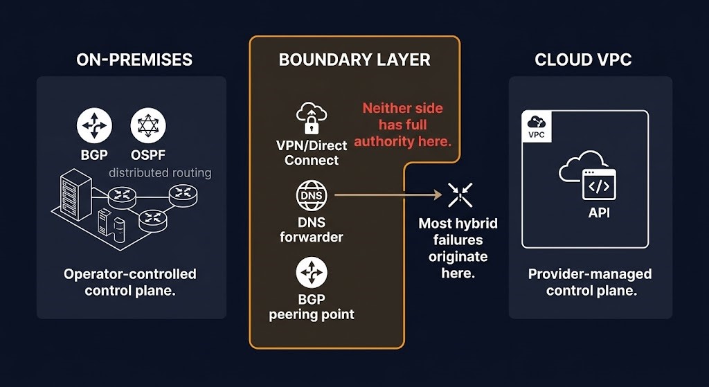
The hybrid connectivity row is equally consequential. Split control plane with undefined authority is not an edge case. It is the default state of every hybrid environment where on-premises routing and cloud VPC configuration are managed by different teams, with different tooling, under different change processes, connected by a boundary layer that neither side fully owns. The failure modes of hybrid networking are almost always in that boundary layer — and the boundary layer is exactly the part that no single team considers their responsibility.
What Modern Networking Architecture Actually Is
Modern networking architecture is three separate systems operating on the same physical and virtual substrate. Most architecture conversations treat them as one. That conflation is where the most expensive network design decisions go wrong.
The control plane is where routing decisions are computed and distributed. BGP peers exchange reachability information. OSPF floods link-state advertisements. An SDN controller pushes flow tables to switches. A Kubernetes CNI controller programs eBPF maps in the kernel. The control plane does not move packets. It decides how packets will be moved — and it distributes that decision to every forwarding element in the network. A control plane failure does not immediately drop traffic. It stops the network from healing. Routes that were learned before the failure continue to be followed. New routes — including the ones that would respond to a link failure, a workload migration, or a policy change — cannot be distributed. The network appears functional while becoming progressively more wrong.
The data plane is where packets actually move. Physical switching fabric. Virtual switching in the hypervisor. eBPF hooks in the kernel. Overlay tunnel encapsulation and decapsulation. A data plane failure drops packets immediately and visibly. It is the failure mode that triggers monitoring alerts and produces clear diagnostic signals. It is also significantly less common than control plane failure as a root cause of enterprise network incidents — which is why the ~80% misconfiguration statistic above is architecturally important. The failure that monitoring catches is usually in the data plane. The failure that causes it is usually in the control plane.
The management plane is where configuration changes are made and network state is observed. SSH sessions to network devices. NETCONF/YANG model pushes. Terraform provider calls to cloud APIs. GitOps pipelines that apply CNI configuration. Prometheus scraping flow metrics. The management plane is not the network. It is the interface through which the network is understood and changed. A management plane failure means operating blind — or being unable to respond to failures in the control plane and data plane when they occur. In hybrid environments, the management plane is consistently the least-designed of the three, which is precisely why it fails most consequentially.
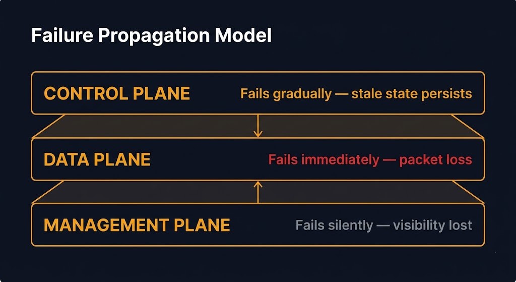
THREE PLANES — THREE FAILURE MODES
| Plane | Function | Failure Behavior | Detection Signal |
|---|---|---|---|
| Control | Routing decisions, policy distribution, reachability state | Gradual — network stops healing, stale state persists | Routing convergence time, BGP session count, controller health |
| Data | Packet forwarding, encapsulation, switching fabric | Immediate — packet loss, visible connectivity failure | Interface errors, drop counters, latency spikes |
| Management | Configuration, observability, change execution | Silent — loss of visibility and response capability | API availability, pipeline execution success, alert delivery |
The failure behavior column is the column that network architecture guides consistently omit. Control plane failure is gradual — the network continues to function on stale state while its ability to respond to change degrades invisibly. Data plane failure is immediate and loud. Management plane failure is silent — the network continues operating while the operator loses the ability to see or change it. These are three distinct failure modes requiring three distinct monitoring strategies. Treating them as one is how teams end up with networks that appear healthy on the dashboard while being genuinely degraded in ways that only surface under the next significant change event.
The Rack2Cloud Network Plane Model
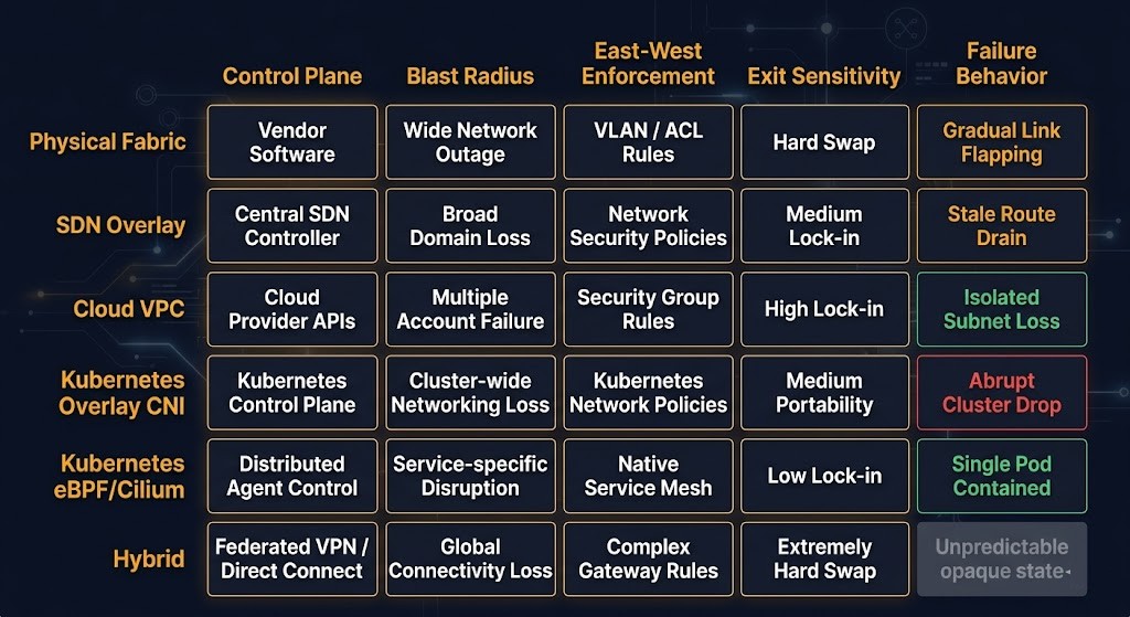
Every modern network architecture belongs to one of six topology classes. Every topology class resolves five architectural variables simultaneously: control plane model, blast radius, east-west enforcement mechanism, exit sensitivity, and failure behavior. The Rack2Cloud Network Plane Model maps them explicitly — not to produce a topology recommendation, but to make the tradeoffs visible at design time rather than at incident time.
| Topology | Control Plane | Blast Radius | East-West Enforcement | Exit Sensitivity | Failure Behavior |
|---|---|---|---|---|---|
| Physical fabric (traditional) | Distributed — BGP/OSPF per device | Zone-bounded | VLAN / ACL | High — hardware-locked | Degrades gradually — distributed state |
| SDN overlay (VXLAN/EVPN) | Centralized controller | Controller-bounded — wide on controller failure | Policy per-flow | Medium — controller-coupled | Fails abruptly — single controller failure point |
| Cloud-native VPC | Provider-managed API | Provider-bounded — opaque | Security group / NACL | High — API and egress dependent | Fails opaquely — provider control plane |
| Kubernetes CNI (overlay) | CNI controller + encapsulation | Cluster-bounded | NetworkPolicy (variable enforcement) | Medium — CNI-coupled | Degrades with CNI controller — pod connectivity affected |
| Kubernetes CNI (eBPF/Cilium) | eBPF kernel maps + controller | Node-local containment + cluster policy | L7 identity-based, kernel-enforced | Low — most portable | Fails locally — node-scoped, contained blast radius |
| Hybrid (on-prem + cloud) | Split — dual control plane | Cross-domain — boundary layer undefined | Policy federation required | Very high — dual dependency | Fails at boundary — neither side has full authority |
The blast radius column and the failure behavior column are the two columns that vendor documentation never highlights. They are also the two columns that determine the operational consequence of every failure event the network will experience over its lifetime.
The SDN overlay failure behavior deserves specific attention: it fails abruptly with wide impact when the controller fails. This is the architectural consequence of centralizing the control plane — the operational simplicity gain is real and significant, but the single controller failure domain is equally real. An SDN controller failure does not degrade the network gradually. It stops the distribution of policy and routing decisions across the entire overlay simultaneously. Traffic continues on existing flow table entries until those entries expire or a topology change requires new ones. At that point, the network’s ability to forward correctly depends entirely on how quickly the controller can be restored. The Sovereign Networking & Control Plane Isolation page covers the specific design patterns for controller redundancy and failure domain containment in SDN environments.
The cloud-native VPC failure behavior — fails opaquely — is the failure mode that catches hybrid architecture teams by surprise. The VPC control plane is not yours. It is a provider-managed API surface. When that API surface is degraded, when provider routing is behaving unexpectedly, or when a provider-side failure is affecting VPC connectivity, the operator has no visibility into the control plane state and no ability to modify it. The network fails in ways that produce no meaningful diagnostic signal on the operator’s side — the failure is in a system the operator cannot inspect. For teams that have modeled their network architecture against the assumption of control plane visibility, this is the assumption that breaks first.
The eBPF/Cilium topology is distinct from other CNI approaches in a way that goes beyond performance. Enforcement is kernel-level and node-local — policy is enforced at the packet level in the kernel without a sidecar proxy or a controller in the data path. The blast radius is correspondingly narrow: a node-level failure affects that node’s workloads without propagating to the rest of the cluster. The Service Mesh vs eBPF analysis covers the architectural comparison between kernel-level enforcement and sidecar-based service mesh in full — including the specific failure modes of each approach.
Physical Fabric and SDN — Where the Control Plane Boundary Moved
Traditional enterprise network architecture distributes the control plane across every device in the network. Each router, each switch, each firewall maintains its own routing state and participates in the control plane protocols — BGP, OSPF, STP — that distribute reachability information across the environment. There is no single point of control. There is also no single point of failure. A device failure affects the routes that device was responsible for. The rest of the control plane continues operating, re-converges, and routes around the failure. The convergence time depends on the protocol and the topology. The blast radius of the failure is bounded by the failed device’s role in the routing domain.
This distributed model has a cost: configuration complexity. Each device is independently configured. Policy changes require touching every device in the policy scope. Audit trails are per-device. Consistency verification requires checking every device individually. For large enterprise network estates — hundreds of devices, thousands of VLANs, complex ACL structures — the operational overhead of maintaining consistency across a distributed control plane is significant. STP in particular introduces failure modes that most architects understand but consistently underestimate in production: topology changes that trigger spanning tree recalculation can cause brief forwarding loops that manifest as application-layer latency spikes with no obvious network-layer cause.
DIAGNOSTIC QUESTION
“If your SDN controller failed right now, how many minutes before your network stops correctly handling new routing and policy decisions — and does your team know that number?”
SDN centralized the control plane to solve the consistency problem. A single controller holds the authoritative network state and pushes configuration to all forwarding elements. Policy changes happen once, at the controller, and propagate automatically. Audit trails are centralized. Consistency verification is a single API query rather than a per-device audit. The operational simplicity gain is genuine. The architectural consequence is equally genuine: the controller is now a single failure domain that spans the entire overlay. What was distributed across hundreds of devices — and could fail partially, gracefully — is now concentrated in a controller cluster that fails abruptly and widely.
The blast radius of an SDN controller failure is bounded by the overlay the controller manages. In environments where the SDN overlay spans the entire data center — which is the operational model that motivated SDN adoption in the first place — the blast radius of a controller failure is the entire data center network’s ability to update routing and policy state. For NSX environments specifically, this is the failure mode that VMware exit planning must model explicitly. The NSX-T to Flow Translator at nsx-to-flow-translator.rack2cloud.com is designed to surface the specific policy translation challenges between NSX micro-segmentation and Nutanix Flow — including the control plane dependency differences between the two models.
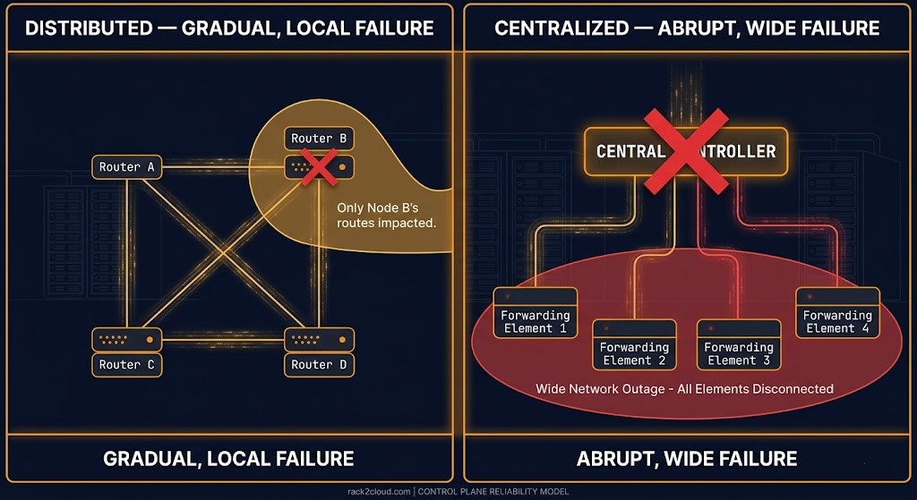
| Dimension | Distributed (BGP/OSPF) | Centralized (SDN Controller) |
|---|---|---|
| Control plane location | Per-device — distributed state | Single controller — centralized state |
| Failure blast radius | Device-bounded — partial degradation | Controller-bounded — wide impact |
| Configuration consistency | Per-device — manual verification | Controller-managed — API-enforced |
| Policy change scope | Per-device touch required | Controller push — single operation |
| Convergence on failure | Protocol-driven — deterministic | Controller-dependent — restoration-critical |
| East-west enforcement | ACL/VLAN — IP-based | Flow table — policy-per-flow |
| Operational model | Device-by-device | Controller operations |
Cloud-Native Networking — The VPC as an Architecture Decision
The VPC is not a network configuration. It is a network architecture commitment. The decisions made at VPC design time — CIDR allocation strategy, subnet segmentation model, security group structure, VPC peering versus Transit Gateway versus PrivateLink — determine the blast radius of every security event, the feasibility of every future topology change, and the cost structure of inter-service communication for the life of the environment. Most of those decisions are made once, under time pressure, by teams that treat the VPC as a connectivity problem rather than an architecture problem.
CIDR exhaustion as an architectural failure mode. The most common silent VPC failure is IP space exhaustion — a failure mode that accumulates invisibly until it prevents new workloads from being scheduled or new subnets from being allocated. In AWS, VPC CIDRs cannot be shrunk after creation. Adding address space requires secondary CIDRs with their own routing and peering implications. In GCP, the global VPC model and per-subnet allocation require explicit secondary range planning for GKE pod CIDRs — a failure mode documented in detail in the GKE Pod IP Exhaustion triage guide. CIDR planning is not a Day-2 concern. It is a Day-0 architecture decision with no low-cost correction path after the fact.
Security groups as distributed firewall, NACLs as perimeter model. Security groups in AWS and Azure operate as stateful, identity-aware firewalls attached to individual resources. A security group rule that permits inbound port 443 from another security group is not an IP range rule — it is an identity rule that follows workloads as they scale, change IPs, and move across availability zones. The failure mode of security group sprawl is structural: as environments grow, security groups accumulate rules that were added reactively, never reviewed, and never removed. The result is a network that looks like it has east-west enforcement but has effectively collapsed into implicit trust because the rule sets are too complex to audit and too risky to clean up. For Azure environments, the Azure Private Endpoint Checker surfaces Private Endpoint configuration gaps and DNS resolution issues that are invisible in standard security group audits.
The API Dependency Trap. The VPC control plane is not yours. Every routing decision, every security group evaluation, every DNS resolution, and every failure response in a cloud-native network depends on provider API availability and provider control plane behavior. This is not a failure mode — it is a design characteristic. It becomes a failure mode when it is treated as an implementation detail rather than an architectural constraint. For workloads with sovereignty requirements, air-gap requirements, or recovery architectures that must function under provider API degradation, the API dependency is a disqualifying characteristic of the cloud-native topology class. The Real World Egress Calculator models the cost dimension of cloud-native networking decisions — the provider dependency and the egress cost structure are two sides of the same architectural commitment.
⚠ ARCHITECTURAL CONSTRAINT
The cloud VPC control plane is not yours. Every change, every recovery, and every failure response depends on provider API availability. Designing a network architecture that assumes control plane visibility and authority — and then running it on a provider-managed VPC — is building two different architectures and calling them one.
VPC connectivity models and their control plane implications. VPC peering, Transit Gateway, and PrivateLink are not equivalent approaches to the same problem. VPC peering is direct — no transitive routing, no shared routing table, blast radius bounded to the two VPCs in the peering relationship. Transit Gateway centralizes routing — which simplifies management of large multi-VPC topologies and introduces a central routing component whose configuration and availability affects every connected VPC. PrivateLink is a service exposure mechanism, not a routing mechanism — it allows specific service endpoints to be accessed privately without VPC peering or routing changes, but it does not create a network path between the VPCs. Each model has a different control plane model, a different blast radius, and a different operational ownership structure. Selecting the wrong one for the environment’s scale and governance model is a topology commitment that is expensive to change after the fact. The Azure Landing Zone vs AWS Control Tower post covers the governance model differences between AWS and Azure networking that determine which connectivity model is appropriate in each environment.
Kubernetes Networking — The CNI as the Network Control Plane in Code
Choosing a CNI is not a plugin selection. It is three simultaneous architectural decisions: your enforcement boundary, your failure domain, and your debugging model. Teams that treat CNI selection as an operational preference — “we’ll use Flannel because it’s simple” — are making all three of those decisions implicitly, without modeling their consequences.
The CNI is the network control plane for every workload in the cluster. It determines how pod-to-pod traffic is routed, where NetworkPolicy is enforced, what happens to cluster networking when the CNI controller fails, and how much visibility an operator has into traffic flows between workloads. None of those characteristics change because the CNI is described as a “plugin.” The plugin label obscures the architectural weight of the decision.
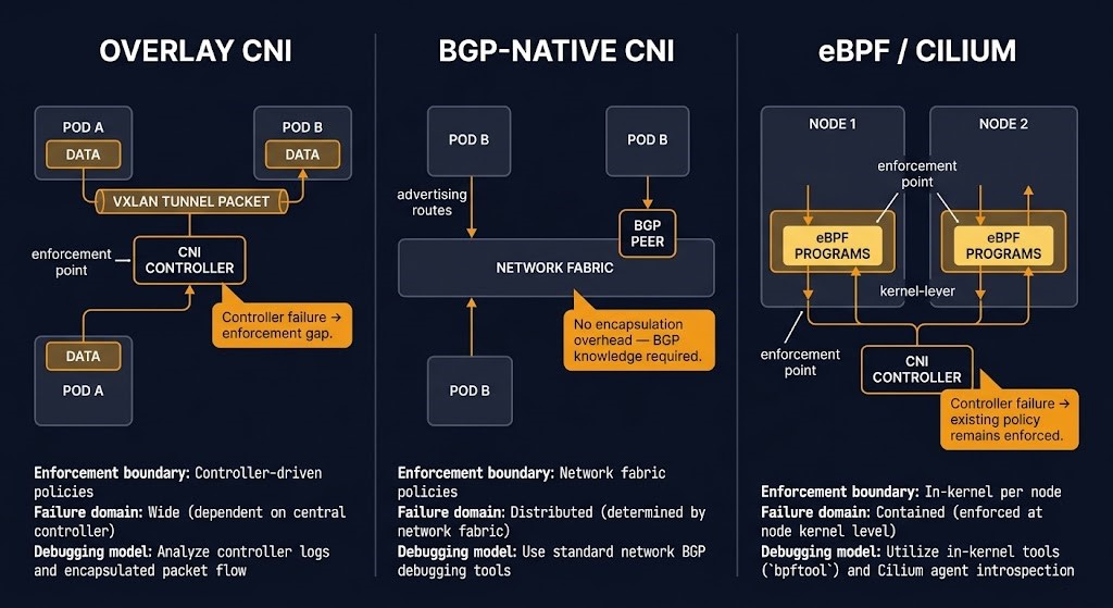
Overlay CNIs (Flannel, Calico overlay, Weave). Overlay CNIs encapsulate pod traffic in VXLAN or similar tunnels, allowing pods across different nodes to communicate using a virtual network layer independent of the underlying infrastructure routing. The operational simplicity is genuine — overlay CNIs work on almost any underlying network without routing protocol configuration. The cost is encapsulation overhead, reduced visibility into the actual traffic path, and a failure domain that includes the overlay management component. NetworkPolicy enforcement in overlay CNIs is handled by the CNI itself, which means a CNI controller failure or misconfiguration can silently remove policy enforcement without producing an obvious error signal.
BGP-native CNIs (Calico BGP, Cilium BGP). BGP-native CNIs advertise pod CIDRs directly into the underlying network routing domain, eliminating the encapsulation overhead of overlay models. Pod traffic is routed natively through the physical or virtual fabric without tunnel wrapping. The failure domain is narrower because there is no overlay management component — the routing state is distributed across the BGP peers. The operational requirement is correspondingly higher: the team operating a BGP-native CNI must have BGP operational knowledge. Route advertisement errors, BGP session failures, or misconfigured peer relationships produce forwarding failures that require routing-layer diagnosis, not CNI-layer diagnosis.
eBPF CNIs (Cilium). eBPF-based networking moves enforcement to the kernel. Policy is compiled into eBPF programs attached to network interfaces and executed at kernel speed, without a sidecar proxy in the data path and without the encapsulation overhead of traditional overlay CNIs. The architectural consequence is that the enforcement boundary moves from the CNI controller to the kernel on each node — which means a CNI controller failure does not remove policy enforcement from running workloads. Existing eBPF programs continue enforcing policy at the kernel layer until the controller can push updates. The failure blast radius is node-local for enforcement and cluster-wide for policy updates. The Service Mesh vs eBPF analysis covers the specific comparison between Cilium’s kernel-level enforcement and traditional sidecar-based service mesh approaches — including the failure modes of each that are invisible in normal operation.
NetworkPolicy as the enforcement gap. NetworkPolicy objects in Kubernetes describe intent. Whether that intent is actually enforced depends entirely on the CNI. Flannel does not enforce NetworkPolicy. Calico enforces NetworkPolicy when configured to do so. Cilium enforces NetworkPolicy and extends it to Layer 7. A cluster running NetworkPolicy objects with a CNI that does not enforce them has security documentation and no security enforcement — a gap that is invisible in standard cluster audits because the NetworkPolicy objects exist and the pods are running. The Kubernetes LLM Security Boundary post covers this enforcement gap specifically in the context of inference workloads, where the consequence of implicit east-west trust is the highest. The Gateway API controller selection and Gateway API operation posts cover the north-south enforcement layer above the CNI — the two enforcement layers interact, and gaps in either produce the same result.
DIAGNOSTIC QUESTION
“Does your CNI enforce every NetworkPolicy object in the cluster — or does it only enforce the subset of NetworkPolicy features it was designed to support? Have you verified the difference?”
Network Segmentation — The Blast Radius Decision
Network segmentation is not a security feature. It is a blast radius decision. The framing matters because it changes what question gets asked at design time. A security framing produces the question: “is this network secure?” A blast radius framing produces the question: “if the worst workload in this environment is compromised, what is the maximum damage that can result from that single event?” The second question produces a better architecture.
Flat networks are not a security posture failure. They are a blast radius decision — a decision that says a successful lateral movement event has access to every other workload in the network segment. For many internal networks carrying low-sensitivity workloads, that may be an acceptable tradeoff given the operational simplicity of not maintaining per-workload or per-tier segmentation. The problem is not flat networks. The problem is flat networks where the blast radius consequence was never explicitly modeled and the sensitivity of the workloads inside the flat segment was never audited.
DIAGNOSTIC QUESTION
“If lateral movement from your most exposed workload reached your most sensitive data store — how many network policy decisions would it have had to bypass? Can you enumerate them right now without a network scan?”
VLAN segmentation and the sprawl failure mode. VLANs create logical isolation boundaries within a shared physical fabric. The blast radius of a workload compromise is bounded by the VLAN — traffic cannot leave the VLAN segment without traversing a Layer 3 boundary where routing and firewall policy are applied. The operational reality of VLAN-based segmentation in mature enterprise environments is VLAN sprawl: the accumulation of VLANs that were created for specific purposes, never decommissioned, and whose current membership and policy relationships are no longer documented. VLAN sprawl is the network equivalent of SDS operational debt. The segmentation structure that was coherent at design time becomes progressively less legible as the environment evolves. Each undocumented VLAN is a potential blast radius expansion that was never explicitly accepted.
Micro-segmentation and the enforcement cost. Micro-segmentation inverts the blast radius model: instead of defining where workloads cannot communicate, it defines where they can. The default posture is deny. Each permitted communication path is an explicit policy decision. A compromised workload can reach only the specific endpoints that policy permits — everything else is denied at the enforcement point. The blast radius of any single compromise is bounded by the explicit policy scope of that workload. The operational cost is real: micro-segmentation policies must be defined, maintained, and kept consistent with actual workload communication patterns. Policies that were correct at deployment become incorrect as workloads change, and incorrect deny policies produce application failures that trace back to policy rather than infrastructure. The Policy Translation: Mapping VMware DRS, SRM, and NSX to Nutanix Flow post covers the specific challenge of migrating micro-segmentation policy between NSX and Flow — a particularly acute version of the maintenance cost problem where existing policy must be translated, not just maintained.
Zero-trust network model. Zero-trust is not a product. It is a segmentation philosophy expressed as an architectural principle: no implicit trust based on network position. A workload inside the data center perimeter does not receive more trust than a workload outside it. Every connection is authenticated and authorized regardless of source network location. The practical implication for network architecture is that identity-based enforcement — enforcement that follows workloads regardless of where they run or what IP address they have — replaces IP-based enforcement as the primary east-west security mechanism. eBPF-based CNIs and service mesh architectures both provide identity-based enforcement at different layers of the stack. The Container Security Architecture page covers the workload identity model that zero-trust network policy depends on.
Hybrid and Multi-Cloud Network Architecture
Hybrid networking does not combine two networks. It creates a third one — the boundary layer — where neither side has full control, neither side has complete visibility, and the failure modes of both sides converge on the same blast radius.
The on-premises control plane is distributed routing with hardware management and human-operated change processes. The cloud control plane is provider-managed VPC routing with API-driven configuration and provider-controlled availability. Connecting them requires a boundary layer — VPN tunnels, Direct Connect or ExpressRoute circuits, SD-WAN fabric — that neither model was designed to operate. The operational responsibility for the boundary layer is consistently the least clearly defined in hybrid environments. Network operations owns on-premises. Cloud operations owns the VPC. The boundary between them is owned by whoever responds to the ticket first.
Site-to-site connectivity models. IPSec VPN is a control plane dependency decision: the VPN tunnels depend on internet routing, and their availability is bounded by the availability of the underlying internet path. For workloads where network availability is a hard requirement, IPSec VPN over the internet introduces a control plane dependency that is outside the operator’s control. Direct Connect, ExpressRoute, and Cloud Interconnect are dedicated private circuits — they remove the internet dependency and provide deterministic bandwidth and latency characteristics. The tradeoff is cost and provisioning time. Neither model eliminates the boundary layer management problem. Both create a connectivity path. Neither defines who is responsible for the routing and policy state at each end of that path. The Deterministic Networking for AI Infrastructure post covers the specific latency and bandwidth requirements that differentiate VPN from dedicated circuit for AI training workload connectivity.
DNS as the management plane for hybrid connectivity. DNS is not a network component. It is the management plane for service discovery in hybrid environments. In a hybrid estate where on-premises services and cloud services reference each other by name, DNS resolution is the control plane that makes those references work. DNS misconfiguration is consistently the root cause of hybrid connectivity failures that present as network connectivity failures. The failure pattern is specific: the network path is intact, the routing is correct, the firewall rules permit the traffic — and the connection fails because the DNS resolver returns the wrong address, returns no address, or enters a recursive loop. The Azure Private Endpoint DNS recursive loop and subnet exhaustion post documents the most common DNS failure pattern in hybrid Azure environments — a failure that presents as a network issue and traces to a DNS configuration gap at the boundary layer.
BGP route leaking at the hybrid boundary. The specific failure mode of hybrid routing that produces the most catastrophic blast radius is route leaking: a misconfigured BGP peer at the boundary between on-premises and cloud causes routes to propagate across the boundary in the wrong direction. An on-premises default route that leaks into the cloud VPC can redirect cloud traffic through the on-premises network, saturating the VPN or Direct Connect link and dropping cloud connectivity. A cloud VPC CIDR that leaks into the on-premises routing domain can create routing loops or black holes for on-premises traffic destined for those addresses. Route filtering at the BGP boundary is a mandatory control, not an optional configuration. The Exit Cost as a First-Class Metric post covers the architectural framing for network design decisions where exit cost and routing dependency are treated as design constraints rather than operational concerns.
The Network Control Plane Test
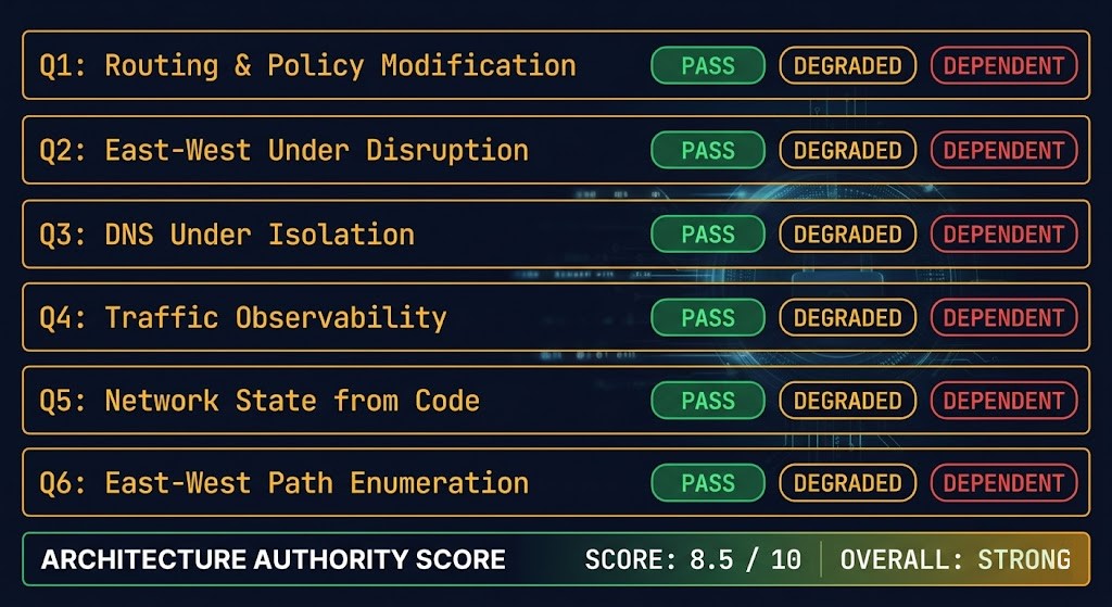
Networking is where “we thought we were in control” fails hardest. The test below is not a checklist — it is a structured interrogation of whether your network architecture is actually under your authority, or whether it only appears to be. Each question has three possible answers. PASS means genuine control. DEGRADED means partial or conditional control. DEPENDENT means the answer depends on something outside your authority.
THE NETWORK CONTROL PLANE TEST
Q1 — Routing and Policy Modification
Can you modify routing tables and enforce policy changes without vendor API dependency or provider support engagement?
PASS — Change is fully operator-controlled via IaC or direct device management | DEGRADED — Some changes require vendor engagement or API availability | DEPENDENT — Provider API or vendor support required for most changes
Q2 — East-West Policy Under Control Plane Disruption
Does east-west policy enforcement continue operating if the control plane controller or API is unavailable?
PASS — Enforcement is kernel-level or hardware-level, independent of controller availability | DEGRADED — Existing policy enforced, new policy cannot be pushed until controller recovers | DEPENDENT — Policy enforcement depends on controller or API availability
Q3 — DNS Resolution Under Network Isolation
Can DNS resolution operate correctly if the network boundary between on-premises and cloud is severed?
PASS — DNS resolvers in each environment operate independently with full local authority | DEGRADED — Local DNS works, cross-environment resolution fails silently | DEPENDENT — DNS resolution for critical services depends on boundary layer availability
Q4 — Traffic Flow Observability
Can you observe traffic flows between workloads without external tooling, provider APIs, or vendor support access?
PASS — Flow telemetry is operator-controlled and available without external dependency | DEGRADED — Partial visibility available; full flow data requires external tooling | DEPENDENT — Traffic visibility depends on provider VPC flow logs or vendor tooling
Q5 — Network State Recovery from Code
Can you rebuild your complete network state — routing, policy, segmentation, DNS — from infrastructure code alone, without relying on configuration history or manual reconstruction?
PASS — All network state is expressed in IaC; a clean apply restores the complete intended state | DEGRADED — Most state is in IaC; some manual configuration exists outside code | DEPENDENT — Significant network state exists only in device configuration history or provider console
Q6 — East-West Path Enumeration
Can you enumerate every permitted network path between your most sensitive workload and the internet — right now, without running a network scan?
PASS — All paths are expressed in policy-as-code; enumeration is a code review | DEGRADED — Most paths are known; some exceptions or legacy rules are undocumented | DEPENDENT — Full path enumeration requires a network scan or vendor tooling
A DEPENDENT answer on Q5 is the most consequential result in this test. If you cannot rebuild your network from code, you do not have a network architecture — you have a configuration history. Configuration histories are not recoverable under the conditions where recovery matters: a failed migration, a control plane corruption event, or a post-incident environment rebuild. The Control Plane Shift: Infrastructure Decisions 2026 post covers this as a cross-infrastructure principle — the network control plane test is the network-layer expression of the same requirement. The CI/CD Control Plane post covers the pipeline architecture required to make network state recovery from code a genuine operational capability rather than a stated intention.
Network Failure Modes
Network architecture failures follow a consistent pattern across topology classes: they accumulate silently in the control or management plane, and surface loudly in the data plane — at exactly the moment when diagnosing and correcting them is most operationally disruptive. The seven failure modes below represent the patterns observed most consistently across enterprise and cloud-native network estates.
Network Architecture in IaC — Where the Control Plane Lives in Code
If you cannot rebuild your network from code, you do not have a network architecture — you have a configuration history. That distinction is not rhetorical. Configuration histories do not survive the conditions where network recovery matters most: a control plane corruption event, a failed migration rollback, a post-ransomware environment rebuild. Infrastructure code survives those conditions because it is stored outside the environment it describes.
The principle applies across every layer of the network stack. Security group rules and VPC configuration that live in Terraform are reviewable, enforceable in CI/CD pipelines, and recoverable from version control. Security group rules that were added through the provider console are configuration history — they exist, they work, and they are invisible to every governance and recovery mechanism the IaC layer provides. The Terraform vs OpenTofu: 2026 Post-BSL Decision post covers the IaC tooling decision that underlies this — the choice of IaC tool matters less than the discipline of ensuring network state is expressed in it.
StorageClass in Kubernetes is to storage what NetworkPolicy plus CNI configuration is to networking. The enforcement model, the failure domain, and the blast radius of the Kubernetes network layer are all determined by what is written in manifests and CNI configuration — not by what teams intend. A NetworkPolicy manifest that describes a deny posture and a CNI that does not enforce it produces the same outcome as having no policy. Admission controllers that validate NetworkPolicy presence but not CNI enforcement capability produce the same false confidence. The PersistentVolumes vs StorageClasses parallel is intentional: the CNI configuration in code is the network’s equivalent of the StorageClass — a manifest-level decision with blast-radius consequences that must be explicitly modeled and validated, not assumed.
Three rules for network architecture in IaC. First: every security group, every routing table entry, every VPC peering relationship, and every NetworkPolicy must be in version-controlled infrastructure code before it is in production. The console is for reading. Code is for writing. Second: network topology variables — CIDR ranges, subnet strategy, peering model, CNI selection — must be named inputs with validation, not hardcoded defaults that the next engineer inherits without understanding the decision they represent. Third: drift detection must be a scheduled CI/CD gate, not a reactive audit. The gap between declared state and observed state is the measure of how much of the network architecture exists only in configuration history. The CI/CD Control Plane post covers the pipeline architecture that makes this enforcement capability operational rather than aspirational.
The Sovereign Drift Auditor is the rack2cloud tool most directly applicable to network architecture drift — it surfaces divergence between declared and observed infrastructure state across the control plane layers that are most commonly managed outside IaC.
What Breaks First
Network failures do not begin at the layer where they are noticed. They begin in the control or management plane and propagate to the data plane by the time monitoring catches them. The sequence is consistent enough to be predictable — and knowing the sequence is what makes diagnosis faster when it matters.
WHAT BREAKS FIRST — IN ORDER
The observability entry is the one that produces the most consequential recovery delays. When the management plane loses visibility before the data plane drops packets, the team is operating blind at exactly the moment when diagnostic speed matters most. The Your Monitoring Didn’t Miss the Incident post covers the structural difference between monitoring that detects failure and observability that explains it — the network management plane is the layer where that distinction is most operationally expensive.
Decision Framework — When Each Network Topology Is the Right Call
Large physical footprints where existing hardware investment is justified. Carrier interconnect environments where BGP operational capability exists. Environments where gradual failure degradation is preferable to abrupt controller failure. Any environment where the distributed control plane’s blast radius containment is a hard requirement.
Data center environments where policy consistency and operational simplicity justify the controller blast radius. Micro-segmentation requirements that are difficult to express in per-device ACLs. VMware NSX environments where the controller investment is already in place and the failure domain is explicitly modeled and accepted.
Cloud-native workloads where provider API dependency is acceptable and egress cost has been modeled. Environments where operational simplicity outweighs control plane visibility. Any workload without sovereignty, air-gap, or recovery-under-provider-failure requirements.
Kubernetes environments where identity-based east-west enforcement is a requirement. Environments evaluating service mesh where sidecar overhead is a constraint. Workloads requiring L7 policy enforcement without proxy injection. Any cluster where the enforcement boundary must survive CNI controller disruption.
The controller failure blast radius has not been explicitly modeled and accepted. The team does not have SDN operational capability to manage the controller lifecycle. The environment has sovereign or air-gap requirements that conflict with centralized controller dependency.
Sovereignty or air-gap requirements prohibit provider API dependency. Recovery architecture must function under provider control plane degradation. Egress cost was not modeled at design time and the workload has high cross-region or cross-service communication volume.
L7 identity-based enforcement is a requirement. The CNI controller failure must not remove enforcement from running workloads. Encapsulation overhead is a measurable constraint for latency-sensitive workloads. NetworkPolicy enforcement coverage must be verifiable without testing.
Explicit ownership of the boundary layer defined before the first circuit is provisioned. DNS resolution tested independently under simulated boundary failure. IaC coverage for both sides of the boundary and the boundary layer itself. Route filtering at the BGP boundary configured and verified.
| Scenario | Topology | Key Signal | Avoid When |
|---|---|---|---|
| Data center SDN, micro-segmentation required | SDN Overlay | Policy consistency justifies controller blast radius | Controller HA not designed; sovereign requirements present |
| Kubernetes-native microservices, L7 enforcement needed | eBPF/Cilium | Identity-based policy, enforcement survives controller disruption | Team has no Cilium operational experience |
| Kubernetes general workloads, simple policy | BGP-native CNI or overlay | Team BGP capability present, encapsulation overhead acceptable | NetworkPolicy enforcement is unverified |
| Cloud-native workloads, no sovereignty requirement | Cloud VPC | Provider dependency acceptable, egress modeled | Air-gap or sovereign recovery requirements present |
| Hybrid on-premises + cloud | Physical fabric + VPC + boundary layer | Boundary layer ownership explicitly defined | Neither side owns the boundary — that is the default state |
| Large physical footprint, existing investment | Distributed fabric | Gradual failure degradation preferred, BGP capability present | Policy consistency at scale is a hard requirement |
| AI training, deterministic low-latency fabric | Physical fabric + BGP-native CNI | No encapsulation, deterministic forwarding | Encapsulation overhead or SDN controller latency is unacceptable |
The network control plane does not operate in isolation. Compute placement decisions affect routing requirements. Storage topology affects data path latency. IaC discipline determines whether the network you have matches the network you think you have. The pages below cover each adjacent layer.
YOU’VE READ THE ARCHITECTURE.
NOW TEST WHETHER YOUR ENVIRONMENT HOLDS.
Your network topology decisions may have been made without explicitly modeling the control plane blast radius, the enforcement gaps, or the hybrid boundary layer. A Network Architecture Assessment maps your current environment against the Network Plane Model and surfaces where the architecture holds and where it doesn’t — before a migration, failure event, or security incident forces it into view.
Network Architecture Assessment
A vendor-neutral review of your network architecture against the Rack2Cloud Network Plane Model — control plane by control plane, failure domain by failure domain, before a migration or failure event forces the conversation.
- > Control plane model and blast radius mapping
- > East-west enforcement gap identification
- > Hybrid boundary layer and DNS dependency audit
- > Network IaC coverage and drift exposure review
Architecture Playbooks. Every Week.
Field-tested network architecture blueprints — CNI failure patterns, SDN blast radius incidents, hybrid DNS failures, and the control plane drift scenarios that compound quietly before they don’t.
- > Kubernetes CNI selection and failure patterns
- > SDN control plane architecture and risk
- > Hybrid boundary layer failure modes
- > Network IaC enforcement patterns
Zero spam. Unsubscribe anytime.
Architect’s Verdict
Modern networking architecture is a control plane discipline. The network you operate is the network the control plane believes exists — and when the control plane’s belief and reality diverge, the gap is invisible until a change event or failure exposes it. Every topology class on this page has a different answer to the question “what happens when this breaks?” and every one of those answers has architectural consequences that should be modeled before the topology is selected, not discovered afterward.
The blast radius column in the Network Plane Model is the variable that determines the scope of every failure event the network will experience over its lifetime. Distributed routing fails gradually and locally. SDN controller failure fails abruptly and widely. Cloud VPC failure fails opaquely. eBPF enforcement failure is node-local. Hybrid boundary failure is cross-domain. None of these are bad answers in isolation. All of them are bad answers when they are not explicitly accepted at design time.
The enforcement gap is where the most expensive security incidents begin. A flat network with VLAN tags is not a segmented network. A NetworkPolicy object without CNI enforcement is not a security policy. A micro-segmentation framework whose policies have drifted from actual workload communication patterns is not east-west enforcement — it is east-west documentation. The gap between what teams believe their network enforces and what it actually enforces is the gap that lateral movement exploits. That gap is not closed by adding security tooling. It is closed by treating enforcement verification as an architectural requirement, not an audit activity.
The hybrid boundary is the highest-risk network state most enterprises are currently running. Not because hybrid is inherently wrong, but because the boundary layer between on-premises and cloud is the part of the architecture that was least explicitly designed, is least clearly owned, and fails in ways that neither side’s monitoring is positioned to explain. Naming that boundary layer as a first-class architectural component — with explicit ownership, explicit IaC coverage, and explicit failure domain modeling — is the change that converts hybrid connectivity from a connectivity problem into a network architecture.
The IaC requirement is not optional. Network configuration that does not live in version-controlled infrastructure code is configuration history. It works until something changes, fails, or needs to be rebuilt — at which point the absence of code becomes an operational liability with no low-cost correction path under pressure.
Frequently Asked Questions
Q1: What is the architectural difference between an overlay CNI and an eBPF-based CNI in Kubernetes?
A: An overlay CNI encapsulates pod traffic in a tunnel (typically VXLAN), routing it across whatever the underlying network provides. Policy enforcement is handled by the CNI’s own controller, which means controller availability affects enforcement capability. An eBPF-based CNI like Cilium compiles policy into programs running in the kernel of each node — enforcement is node-local and continues operating even if the controller is unavailable. The blast radius of an eBPF CNI failure is node-scoped for enforcement; an overlay CNI failure can affect enforcement cluster-wide. The debugging model is also fundamentally different: overlay CNI failures trace to encapsulation and controller state; eBPF CNI failures trace to kernel program state and BPF map contents — a different diagnostic skill set.
Q2: When does micro-segmentation justify its operational overhead?
A: When the blast radius consequence of flat network compromise has been explicitly modeled and found unacceptable — not before. The question is not “is micro-segmentation more secure?” The answer to that is always yes. The question is “what is the cost of a successful lateral movement event in this environment, and does that cost justify the ongoing operational cost of maintaining accurate micro-segmentation policy?” For environments where the most sensitive workloads share a network segment with internet-facing services, micro-segmentation is architecturally necessary. For environments where all workloads carry equivalent sensitivity, the blast radius consequence of a flat network may be acceptable given the operational cost reduction.
Q3: How should VPC CIDR allocation be treated as an architecture decision?
A: CIDR ranges cannot be shrunk after creation in most cloud providers. Secondary CIDRs add routing and peering complexity. Subnet sizing determines the maximum workload density per availability zone. The CIDR allocation decision sets the upper bound on environment scale and the lower bound on subnet granularity — both permanently. The correct approach is to treat CIDR allocation as an architecture document, not a provisioning form: document the expected maximum workload count, the subnet strategy by workload type and availability zone, the secondary range requirements for Kubernetes pod CIDRs, and the peering or Transit Gateway topology implications of the chosen ranges. Any CIDR allocation that cannot be justified against those documented requirements is a future constraint being silently accepted.
Q4: What makes hybrid networking the highest-complexity network state?
A: The split control plane. On-premises routing is distributed BGP/OSPF with hardware management. Cloud VPC routing is provider-managed with API configuration. The connection between them requires a boundary layer — VPN, Direct Connect, ExpressRoute — that operates under neither control model and is typically owned by neither team. The failure modes of the boundary layer are often not covered by either environment’s monitoring. DNS resolution across the boundary adds a management plane dependency that fails in ways that present as network failures. Route leaking at the BGP boundary can produce blast-radius events in both environments simultaneously. Hybrid is not inherently wrong. It is the highest-complexity state because it adds a third network architecture — the boundary layer — to the two it is connecting, and that third architecture is the one that is least explicitly designed.
Q5: What is the difference between a NetworkPolicy object and east-west enforcement in Kubernetes?
A: A NetworkPolicy object is a declaration of intent. East-west enforcement is the actual mechanism that acts on that intent. The gap between them depends entirely on the CNI. Flannel does not enforce NetworkPolicy. Calico enforces most NetworkPolicy features when configured correctly. Cilium enforces NetworkPolicy and extends it to Layer 7. A cluster with NetworkPolicy objects and a non-enforcing CNI has security documentation and no security enforcement — a state that passes a visual audit of the cluster’s manifest files and fails a connection test between supposedly isolated workloads. Verifying enforcement requires testing an expected-deny connection, not reviewing policy object presence.
Q6: When does SDN controller centralization become a blast radius problem?
A: When the controller manages an overlay that spans more of the environment than an acceptable single failure domain. In a small data center where the SDN overlay covers 20 racks, a controller failure affects 20 racks. In a large enterprise where the SDN overlay covers the entire campus and data center network, a controller failure affects the entire campus and data center network simultaneously. The blast radius grows with the scope of the overlay the controller manages — and the scope of the overlay is typically defined by the operational simplicity goal that motivated SDN adoption in the first place. The architectural requirement is explicit controller HA design with documented failure blast radius, not assuming that controller redundancy eliminates the blast radius consequence.
Q7: How should network architecture decisions be expressed in IaC?
A: Every security group, routing table entry, VPC peering relationship, and NetworkPolicy must be in version-controlled infrastructure code before it is in production. Network topology variables — CIDR ranges, subnet strategy, peering model, CNI selection — must be named inputs with validation, not hardcoded defaults. Drift detection must be a scheduled CI/CD gate that diffs declared state against observed state. The test is simple: given a complete loss of the current environment, can the network be rebuilt from the code in the repository, without relying on device configuration exports, provider console history, or team knowledge? If the answer is no, the network architecture is partially undocumented — and the undocumented part is the part that will be missing when it is needed most.