Recovery Ends the Outage. It Doesn’t End the Incident.
THE RECOVERY ENGINEERING SERIES
Business continuity planning assumes recovery ends the incident. In distributed systems, recovery frequently begins the next one. The gap between those two statements is where most post-recovery outages originate — and where most continuity plans have no coverage at all.
The continuity cascade is not about secondary failures propagating from the original failure. It is about restoration-induced instability: the recovery operation itself as the destabilization event. Adjacent systems don’t fail because the primary system failed. They fail because they adapted to the degraded state — and recovery broke the equilibria they had built.
This is the failure pattern that keeps incident commanders on bridge calls after the systems show green. The monitoring says restored. The application says healthy. The business says the outage is over. And then, over the next six to eighteen hours, things start breaking in ways nobody can trace back to the original incident.
Recovery Isn’t Restoration
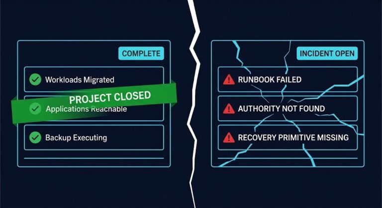
A system can be technically recovered without being operationally restored. These are not the same condition, and treating them as equivalent is the root assumption that makes continuity cascades possible.
Technical recovery means the failed component is back online — the database cluster is accepting connections, the service is responding to health checks, the deployment is showing running pods. Operational restoration means the environment has returned to the state it was in before the failure: all dependencies are reconnected, all state is consistent, all downstream systems are receiving the traffic and data they expect, and all the adaptive behaviors triggered by the outage have been reversed.
Most disaster recovery architectures define “resolved” at the technical recovery milestone. The on-call declares the incident closed. The post-mortem is scheduled. The stakeholder communication goes out. And the operational restoration — which may take hours more, and which carries its own instability risks — happens in the background, unmanaged, because it isn’t recognized as part of the incident.
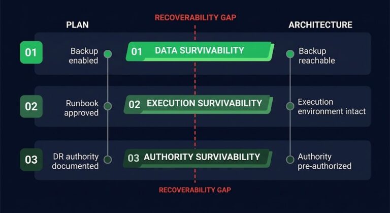
Everything in this article assumes technical recovery itself succeeded — that the platform executing recovery was reachable, and the people running it had the access and authority to do so. That assumption deserves naming, because it is frequently false in real incidents. Whether the recovery platform and execution authority survive the incident in the first place is a separate, earlier question from the one this article addresses. Disaster recovery authority — who holds declaration rights, who can approve failover, and who can release production systems — is the human layer that continuity plans most often leave implicit. Recovery Platform Architecture, the second stage in the Data Protection & Resiliency Learning Path, covers that earlier question — whether recovery can be executed at all. The continuity cascade describes what goes wrong after execution succeeds.
The continuity cascade is what happens in that gap. Not because anyone made a mistake. Because the architecture treated technical recovery and operational restoration as the same event, and designed nothing for the transition between them.
The Environment Adapted to the Failure
The most important concept in understanding continuity cascades is one that almost no continuity literature addresses: during an outage, adjacent systems don’t stay frozen in the state they were in before the failure. They adapt. They find new equilibria. They make the degraded condition workable.
This is Adaptive Stability — the tendency of distributed systems to stabilize around failure conditions rather than simply degrading. It is not a bug. It is how well-designed systems survive partial failures. But it is exactly what makes recovery dangerous.
Consider what happens in a typical database cluster failure. Traffic routes to read replicas. Caches extend their TTLs because the authoritative source is unavailable. Async queues begin accumulating backlog, buffering the work that can’t be processed. Auth services switch to degraded token validation — accepting tokens they would normally reject because the full validation path is broken. Retry suppression activates across dependent services to prevent cascading load. Autoscalers adjust to the new traffic distribution.
None of these are failures. They are correct adaptive behaviors. Each one makes the system more stable in the degraded state. And each one becomes a liability the moment the primary system recovers.
When the database cluster comes back online: the read replicas are now authoritative in the cache, and the primary resumes with a replication lag window that creates state inconsistency. The queues replay — but out of order, because the consumers haven’t reestablished their sequence guarantees. The cache invalidation storm begins as every extended TTL expires simultaneously. Auth tokens that were accepted during degraded validation no longer match the restored signing keys. Traffic floods back to the primary from every direction at once, because the retry suppression logic wasn’t designed to release gradually. The autoscaler is positioned for the degraded traffic distribution, not the restored one.
The outage ended. The cascade began.
The longer the outage lasted, the more thoroughly adjacent systems adapted to the degraded condition. Recovery then becomes a destabilization event proportional to the adaptation that preceded it. A five-minute outage has minimal adaptive state to unwind. A two-hour outage has built equilibria across every layer of the stack — and recovery breaks every one of them simultaneously. As the Incident Recovery post covers, the incident management process itself reinforces this problem by treating the technical recovery milestone as the close event — which means the operational restoration phase runs without incident ownership, monitoring, or escalation paths.
What the Continuity Cascade Actually Is
The term “cascade failure” is used loosely in infrastructure writing, and it’s worth being precise about what a continuity cascade is and what distinguishes it from standard cascade failures.
A traditional failure cascade follows a propagation pattern: A breaks, which causes B to break, which causes C to break. The failure moves forward through dependency chains. The origin is a component failure, and the cascade is the failure propagating through the graph.
A continuity cascade follows an inversion pattern. The primary component has recovered — A is back. B and C break because A recovered. Not because A failed. Because A came back.
The cause is restoration, not failure. The origin is a recovery event, not a component fault. The propagation mechanism is not failure dependency but adaptive state mismatch — B and C were relying on assumptions that A’s recovery invalidated.
This distinction matters because it means the failure mode is completely invisible to the tools built to detect traditional cascade failures. Your dependency monitoring won’t show it. Your failure correlation engines won’t catch it. Your incident detection logic is looking for broken components, and everything looks healthy. The failure surfaces as degraded behavior in systems that are all technically running — because the instability isn’t a failure, it’s a mismatch between the restored state and the adapted state.
The Four Recovery Triggers Nobody Designs For
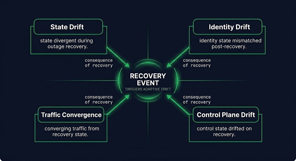
Continuity cascades originate in four distinct domains. Each represents a category of adaptive state that recovery invalidates — and that most recovery procedures don’t account for.
State Drift is the mismatch between the state the recovered system holds and the state that downstream systems expect it to hold. Queue offsets accumulated during the outage don’t match what consumers are positioned to receive. Cache invalidation windows are misaligned with the recovery timing. Replication lag assumptions were calibrated against the pre-failure state. Replay ordering guarantees break when consumers re-attach in a different sequence than they detached. Stale coordination locks held by systems that adapted around the outage prevent clean reattachment. State drift is the most common trigger and the hardest to detect because it surfaces as data inconsistency rather than component failure.
Identity Drift is the mismatch between the identity surface of the recovered system and the trust relationships that downstream systems built during the outage. Token signing keys may have rotated during recovery or restoration to a backup. mTLS trust chains may have changed if certificate material was part of the recovery scope. Kerberos tickets accumulated during the outage may be invalid against the restored key distribution center. Workload identity rebinding — common in cloud-native environments — creates a new identity surface that existing sessions don’t recognize. Restored secrets older than the active clients they’re supposed to authenticate are a particularly common source of post-recovery auth failures: the secret is correct for the restored system, but the clients were issued newer material during the outage that the restored system doesn’t know about.
Traffic Convergence is the storm that happens when traffic control mechanisms release simultaneously. Re-entry storms occur when every retry-suppressed service resumes retrying at the same moment the primary becomes available. Cache cold starts hit every system simultaneously as extended TTLs expire and every node needs to refresh from the now-restored authoritative source. Synchronized retry resumption creates demand spikes that can exceed the capacity of the just-recovered system. Traffic convergence is often mistaken for a capacity problem with the primary system — the recovering system is overwhelmed — when the actual cause is the simultaneous release of adaptive traffic controls that were never designed to release gradually.
Control Plane Drift is the mismatch between the orchestration state that recovered systems re-enter and the orchestration topology that was active during the outage. Autoscaler assumptions drifted during the outage — scaling decisions were made against a different traffic distribution and workload pattern than the one the recovered system re-enters. Policy engines updated during failover now govern a system that was configured for the pre-failover state. Service discovery topology changed — new endpoints registered, old ones removed — and restored services attempt to re-register into a topology that was reconfigured around their absence. The recovered service is technically running, but operating against an orchestration state that was rebuilt without it.
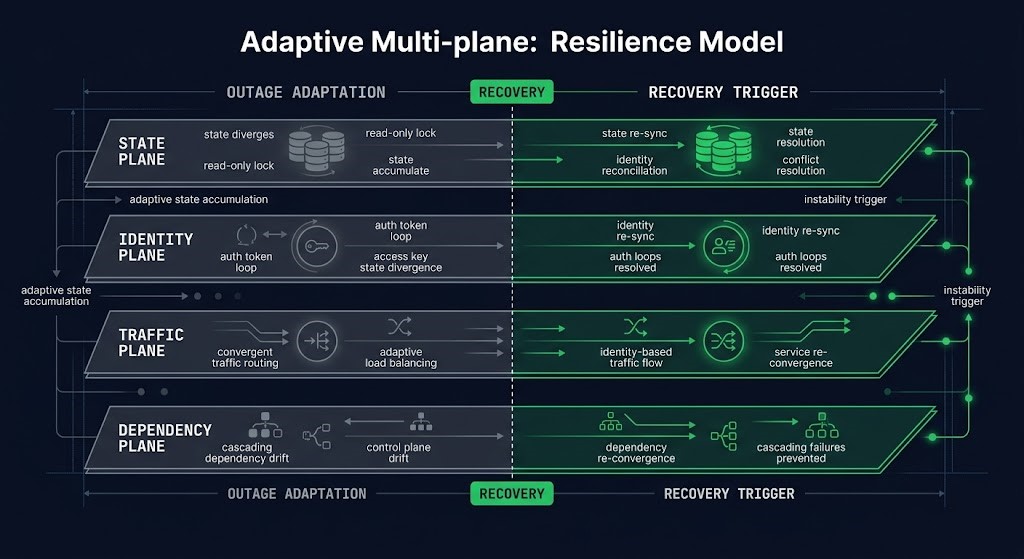
The Continuity Cascade Model
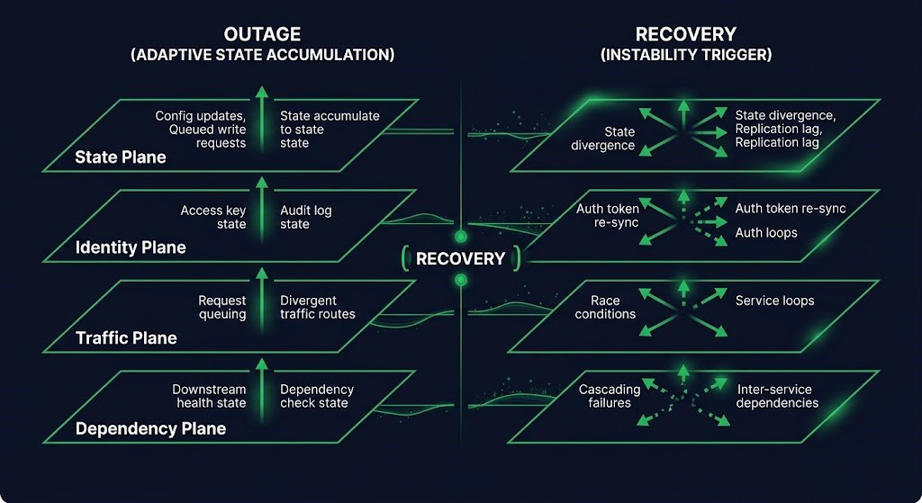
The Continuity Cascade Model organizes post-recovery instability into four planes. Each plane defines a domain where adaptive state accumulates during an outage and becomes a liability at recovery. For each plane: what it owns, how it adapts during an outage, what the recovery trigger looks like, and what the detection test is.
THE CONTINUITY CASCADE MODEL
STATE PLANE
Owns: data consistency, queue ordering, replication state, cache coherence, coordination locks. Adapts by: extending TTLs, accumulating backlog, diverging replica state. Recovery trigger: state mismatch between restored primary and adapted downstream consumers. Detection: replay errors, cache invalidation storms, lock contention spikes immediately post-recovery.
IDENTITY PLANE
Owns: token signing keys, mTLS trust chains, Kerberos tickets, workload identity bindings, secrets material. Adapts by: switching to degraded validation, accepting tokens outside normal policy. Recovery trigger: restored identity surface doesn’t match material issued during outage. Detection: auth failures on specific services only, intermittent 401/403 errors, cert renewal failures in the hours following recovery.
TRAFFIC PLANE
Owns: load distribution, retry logic, cache warming, traffic shaping. Adapts by: activating retry suppression, rerouting to replicas, adjusting autoscaler targets. Recovery trigger: simultaneous release of adaptive traffic controls creates demand spike against recovering system. Detection: load spike on primary immediately after recovery declaration, despite no change in upstream demand.
DEPENDENCY PLANE
Owns: service discovery, orchestration topology, policy engine state, autoscaler positioning. Adapts by: reconfiguring topology around absent services, updating policy for degraded state, repositioning autoscalers for degraded workload distribution. Recovery trigger: recovered service re-enters an orchestration topology configured around its absence. Detection: service registration conflicts, policy violation errors on recovered service, autoscaler instability post-recovery.
The model is useful because it gives incident commanders a structured checklist for the recovery transition — not for the failure itself, but for the moment after the systems show green. Each plane has a specific set of signals to check before declaring operational restoration, and a specific set of controls to sequence before releasing traffic.
Recovery Order Is an Architectural Decision
Most continuity cascades are not caused by any single component failing to recover. They are caused by the order in which components recover — and by recovery procedures that treat all components as equivalent and restore them simultaneously.
Systems rarely fail all at once. Most disaster recovery architectures are designed for the failure event — not the recovery sequence. A database cluster fails. The application tier adapts. The caching layer adapts. The auth layer adapts. Each adaptation happens at a different time, in response to a different failure signal, and creates a different category of state change. Recovery that restores everything simultaneously re-presents all those state mismatches at the same moment.
RECOVERY ORDERING RULE
“Identity plane before traffic plane. State reconciliation before consumers resume. Dependencies before dependents.”
The correct recovery order follows the dependency structure of the adaptive state, not the dependency structure of the original failure. Identity must be warm before traffic resumes — auth failures on restored services are guaranteed if tokens and certs aren’t validated before the first request arrives. State must be reconciled before consumers re-attach — queue ordering failures and cache inconsistencies are guaranteed if consumers start reading before the primary has confirmed its replication state. Dependencies must re-register before dependents route to them — service discovery conflicts are guaranteed if a service attempts to re-enter a topology before the services it depends on have confirmed their availability in the restored state.
STAGED RECOVERY SEQUENCE
01 — IDENTITY PRE-WARMING
Token and certificate validation before traffic is restored. Confirm signing key alignment, mTLS chain validity, and workload identity rebinding before any downstream service is allowed to route to the recovered component.
02 — STATE RECONCILIATION CHECKPOINT
Replication lag confirmed closed. Queue offset alignment verified. Cache invalidation triggered in controlled sequence rather than simultaneous TTL expiry. Coordination locks released. State reconciliation must complete before consumers re-attach.
03 — DEPENDENCY CONVERGENCE
Service discovery re-registration confirmed. Policy engine state updated for restored topology. Autoscaler targets recalibrated. Dependent services allowed to re-attach only after dependency service discovery is confirmed stable.
04 — CONTROLLED TRAFFIC RE-ENTRY
Retry suppression released gradually, not simultaneously. Traffic re-entry shaped to prevent re-entry storm. Load ramp rather than full cutover. Monitoring baseline re-established before declaring operational restoration.
The gap in most recovery plans is that stages 01 through 03 don’t exist. Most plans go directly from “system is responding to health checks” to stage 04 — and skip the three stages that prevent the cascade.
Designing for Re-entry Stability
Recovery procedures that prevent continuity cascades are not more complex than standard recovery procedures. They are structurally different. The difference is not more steps — it is different principles governing the steps.
Recovery must be staged, not binary. A binary recovery model — system is down, system is up — has no concept of a transition state. Staged recovery inserts a pre-traffic phase between technical recovery and operational restoration. The system is running, but not yet receiving production traffic. That phase is where identity pre-warming, state reconciliation, and dependency convergence happen.
Restored systems must reconcile before serving. State checkpoints at the application layer, not just at the infrastructure layer. A health check that returns 200 tells you the process is running. It doesn’t tell you the replication lag is closed, the queue offset is consistent, or the cache is coherent. Recovery validation needs application-layer state checks, not just infrastructure health probes.
Identity surfaces must warm before failback. Token and certificate pre-validation as a recovery step, not an afterthought. In cloud-native environments, workload identity rebinding should be automated and confirmed before traffic routing changes. The test is simple: can the recovered service authenticate to its downstream dependencies with the identity material it has? That test should be automated and run before the traffic plane is modified.
Dependencies must re-attach gradually. Dependency convergence sequencing — the order in which services re-register and re-attach — should follow the same dependency graph as the original architecture. Bottom-up re-attachment, not simultaneous. The services with no dependencies re-register first. The services that depend on them re-attach after confirmation. Traffic gates between each layer prevent premature routing before downstream services are ready.
DESIGN PRINCIPLE
A recovery plan that only describes how to restore components has not described how to restore the system. Component restoration and system restoration are different engineering problems — and most runbooks only solve the first one.
The Retry Storm post covers the specific failure pattern where retry logic becomes the destabilization mechanism — the traffic convergence trigger in detail. The Incident Recovery post covers why the incident management process itself creates the conditions for continuity cascades by closing the incident at technical recovery rather than operational restoration. How far a system can degrade before recovery becomes structurally impossible — and how to design the floor — is what The Degradation Ladder covers next in this series.
Architect’s Verdict
Technical recovery and operational restoration are not the same event. Every continuity plan that treats them as equivalent has a blind spot in the recovery transition — the phase where adaptive state accumulated during the outage is unwound, and where every piece of that adaptive state is a potential cascade trigger.
The Continuity Cascade Model doesn’t describe a new failure mode. It describes a failure mode that has always existed in distributed systems but rarely gets named: the environment that stabilized around a failure can be destabilized by the recovery. Adjacent systems adapted. Recovery broke those adaptations. The instability surfaces as degraded behavior in systems that are all technically running — which is exactly why it’s invisible to the tooling built to detect component failures.
The recovery ordering rule is the design lever: identity before traffic, state reconciliation before consumers, dependencies before dependents, traffic re-entry staged rather than binary. These aren’t additional steps in the runbook. They are the engineering answer to the question that most runbooks don’t ask — not “how do we restore the component?” but “how do we restore the system?”
The most dangerous moment in a distributed outage is frequently the moment operators believe the outage is over.
Additional Resources
Editorial Integrity & Security Protocol
This technical deep-dive adheres to the Rack2Cloud Deterministic Integrity Standard. All benchmarks and security audits are derived from zero-trust validation protocols within our isolated lab environments. No vendor influence.
R.M.
Senior Solutions Architect with 25+ years of experience in HCI, cloud strategy, and data resilience. As the lead behind Rack2Cloud, I focus on lab-verified guidance for complex enterprise transitions. View Credentials →
Get the Playbooks Vendors Won’t Publish
Field-tested blueprints for migration, HCI, sovereign infrastructure, and AI architecture. Real failure-mode analysis. No marketing filler. Delivered weekly.
Select your infrastructure paths. Receive field-tested blueprints direct to your inbox.
- > Virtualization & Migration Physics
- > Cloud Strategy & Egress Math
- > Data Protection & RTO Reality
- > AI Infrastructure & GPU Fabric
Zero spam. Includes The Dispatch weekly drop.
Need Architectural Guidance?
Unbiased infrastructure audit for your migration, cloud strategy, or HCI transition.
>_ Request Triage Session