

VIRTUALIZATION STORAGE AND NETWORK ARCHITECTURE
vSAN topology, distributed switching, and failure domain design — where storage protocol, switching fabric, and recovery boundaries resolve into a single architectural decision.
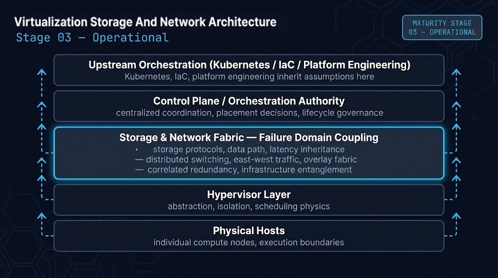
MATURITY STAGE POSITION
- Current Stage: Operational — Maturity Stage 03 of 05
- Primary Architectural Concern: How storage protocol selection, distributed switching, and topology design couple infrastructure components into correlated failure domains — and how those couplings propagate through the control plane authority established in Stage 2
- Primary Failure Mode: Storage and network treated as independent infrastructure layers, when they are correlated failure domains the control plane inherits. The cluster looks redundant; the failure domain is structurally singular
- Stage Outcome: Architects completing this stage can model storage and network architecture as coupled failure domains, identify correlated redundancy before it converts a single fault into a cluster event, and sequence topology decisions around recovery survivability rather than vendor defaults
- Next Stage: Strategic — Deterministic Platform Operations
Virtualization Storage and network architecture is the stage at which virtualization stops behaving like a platform and starts behaving like entangled infrastructure. The control plane authority established in Stage 2 governs scheduling, lifecycle, and placement — but it inherits whatever failure correlations the storage fabric and network topology underneath it carry. Those correlations are invisible during steady-state operation. They surface as cluster-wide events the moment a single component fails inside a shared domain the architecture never declared.
This stage exists because most virtualization architectures treat storage and network as independent infrastructure layers — selected by vendor reference, sized by capacity, validated by performance benchmarks. That framing is wrong at the Operational maturity level. Storage protocol selection, distributed switching design, and topology decisions are not infrastructure-layer choices. They are failure domain decisions. They determine blast radius before any workload runs. They determine migration risk before any cluster expands. They determine recovery ceiling before any DR plan is written. The cluster that looks redundant on the procurement diagram is structurally single-domain the moment its redundant fabrics share a switching plane, its redundant storage shares a synchronization layer, or its redundant hosts share a quorum dependency. This stage is where that gap — between perceived redundancy and architectural resiliency — gets exposed and closed.
>_ WHY THIS STAGE EXISTS
Most virtualization outages blamed on “the cluster” are actually undeclared storage or network failure domains propagating upward through the control plane. The control plane did not fail. It faithfully executed the coordination behavior it was designed for — against an infrastructure layer whose correlated dependencies were never made explicit.
This stage exists because every operational virtualization platform inherits a failure domain from how its storage and network are integrated. Stage 3 makes that inheritance explicit — names it, maps it, and treats topology as the architectural decision it actually is.
WHAT THIS STAGE IS NOT
01 — NOT A vSAN VS. EXTERNAL STORAGE DEBATE
The architectural question is failure domain coupling — not whether storage lives inside the cluster or outside it. HCI and external arrays both produce correlated failures; they just couple along different boundaries.
02 — NOT A NETWORKING CERTIFICATION TRACK
The focus is east-west traffic amplification, switching fabric coupling, and isolation topology — not protocol exam objectives, vendor-specific feature recall, or configuration walkthroughs.
03 — NOT A VENDOR REFERENCE ARCHITECTURE WALKTHROUGH
Vendor reference architectures are starting points, not architectural decisions. Stage 3 covers what those references assume — and what those assumptions cost when the deployment environment violates them.
04 — NOT A PERFORMANCE TUNING GUIDE
Performance is a steady-state concern. This stage covers failure-state behavior — what storage and network topology do when something breaks, not how fast they run when everything is fine.
>_ READING DEPTH
OPERATIONAL STAGE — VIRTUALIZATION STORAGE AND NETWORK ARCHITECTURE READING SCOPE
| Article | Architectural Focus | Est. Read | Pillar |
|---|---|---|---|
| Enterprise Storage Architecture | SDS mechanics, data path ownership, storage protocol selection, latency inheritance | 14 min | Virtualization |
| Modern Networking Architecture | East-west traffic, overlay design, distributed switching, fabric topology | 13 min | Virtualization |
| Sovereign Networking & Control Plane Isolation | Network failure domain boundaries, isolation architecture, sovereign segmentation | 12 min | Virtualization |
| The Configuration Drift Discovery During a Drill | Recovery topology asymmetry — when DR architecture inherits production’s correlated failures | 10 min | Data Protection |
>_ WHERE TO ENTER THIS STAGE
Start here if you completed Stage 2 and are ready to move from orchestration authority to the failure domain architecture beneath it — the core concern of virtualization storage and network architecture at the Operational maturity level — if your current understanding of storage and networking is primarily procedural (how to configure vSAN policies, set up distributed switching, allocate VLANs) rather than architectural (what those decisions couple together and what those couplings cost when something fails).
You can likely skip ahead to Card 3 if:
- You can model east-west traffic patterns for a 16+ node cluster without external tooling
- You have designed a production distributed switching topology and reasoned about its failure modes before deployment
- You have personally seen at least one storage protocol decision convert into a cluster failure domain — not in a vendor postmortem, but in your own environment
If those three statements describe you, Card 3 (Failure Domain Coupling) is the correct entry point. If any of them require translation, start at Card 1 — Storage Protocols & Data Path Authority.
>_ ARCHITECTURE MATURITY POSITION
| Stage | Level | Focus | Slug |
|---|---|---|---|
| 01 — Virtualization Foundations | Foundation | Abstraction mechanics, scheduling physics, failure-domain vocabulary, control plane inheritance | /virtualization-foundations/ |
| 02 — Control Plane Architecture | Operational | Cluster coordination, scheduling authority, lifecycle governance, platform authority models | /virtualization-control-plane-architecture/ |
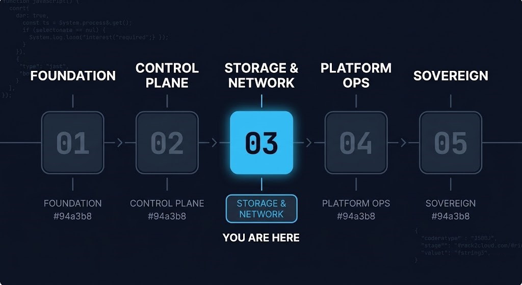
| 03 — Storage & Network Integration ← YOU ARE HERE | Operational | Storage fabric, distributed switching, failure domain coupling, infrastructure entanglement | /virtualization-storage-network-architecture/ |
| 04 — Deterministic Platform Operations | Strategic | Day-2 governance, cost architecture, operational determinism | /virtualization-day-2-governance/ |
| 05 — Post-VMware Strategic Architecture | Sovereign | Platform independence, migration authority, exit strategy | /virtualization-sovereign-architecture/ |
>_ READING SEQUENCE
The five cards below are dependency-ordered along a causal chain — storage defines synchronization behavior before networking does, networking only becomes meaningful once storage coordination exists, and failure domain coupling can only be analyzed after both have been mapped. Card 5 is the bridge — it closes the Operational stage by establishing recovery survivability as the gateway concern into Strategic maturity, Data Protection, and Sovereign architecture.
Storage Protocols & Data Path Authority
Storage protocol selection — block, file, object, or software-defined — is the first architectural decision in this stage because it defines the synchronization behavior every other component inherits. Data path ownership determines where I/O contention surfaces under failure conditions. Protocol choice determines latency inheritance: synchronous replication imposes latency constraints the network must satisfy, asynchronous replication imposes consistency constraints the recovery topology must absorb. SDS mechanics make storage a distributed system in its own right — with its own quorum, its own state convergence, its own failure modes that the virtualization control plane treats as opaque infrastructure. None of those properties are vendor features. They are architectural commitments made the moment the protocol is selected.
East-West Traffic & Distributed Switching
Once storage coordination exists, networking becomes the second-order failure domain. East-west traffic — the cluster-internal flow between hosts, between storage nodes, between control plane components — grows non-linearly with cluster density and workload mobility. Distributed switching architecture determines whether that growth stays survivable or amplifies into instability. Overlay design (VXLAN, Geneve, NSX, Open vSwitch) introduces encapsulation overhead and control-plane dependencies the underlay never sees. Mobility traffic — vMotion, live migration, replication streams — competes with workload traffic on the same fabric, on the same uplinks, often through the same physical switches. The fabric is not the network. It is the failure-correlation surface that connects everything above it.
Failure Domain Coupling & Infrastructure Entanglement
This is the card the stage exists to deliver. Storage protocols and distributed switching each define their own failure domains. Coupled together inside the same orchestration authority, they create a third class of failure — correlated, propagating, structurally invisible until it triggers. Stage 3 is where virtualization architecture becomes entangled infrastructure architecture — storage, networking, orchestration, and recovery behavior stop operating independently. This is what we name Infrastructure Entanglement: the architectural condition where components that appear redundant on a topology diagram share an undeclared dependency — a latency domain, a switching fabric, a coordination layer, a quorum surface — and therefore fail together. HCI couples storage and compute under one cluster boundary. Shared underlay couples east-west and storage replication under one fabric. Distributed control planes couple quorum sensitivity to network partition behavior. The redundancy is real. The resiliency is illusory. Redundancy is not resiliency when the redundant systems inherit the same latency domain, switching fabric, or storage coordination layer.
STORAGE AND NETWORK INTEGRATION FAILURE PATTERNS
— Correlated Redundancy Failures —
— Topology Survivability Failures —
Isolation & Sovereign Boundaries
Once entanglement is named, the architectural response is isolation — but isolation that is structural, not procedural. Segmentation through VLANs and firewall rules is operational hygiene; it is not a failure domain boundary. True isolation means dedicated switching fabrics for replication traffic, control plane networks that cannot share quorum surfaces with workload networks, sovereign network segments where the recovery environment cannot inherit production’s correlated failures. Blast radius reduction is the design objective. Recovery boundary design is the deliverable. The sovereign networking model from Stage 2’s pillar work applies directly here — isolation domains exist to make failure containment a property of the topology, not a hope.
Recovery Ceiling & Platform Survivability
The choices made in Cards 1 through 4 collectively define the platform’s recovery ceiling — the upper bound of what DR, failover, and migration can achieve regardless of how much investment goes into recovery tooling above this layer. Storage protocol determines replication semantics. Fabric topology determines failover behavior. Quorum sensitivity determines partial-failure outcomes. Isolation design determines whether recovery environments inherit production’s correlated failures or escape them. Recovery topology asymmetry — when production and recovery environments couple along different boundaries — is the single most common reason DR drills succeed and DR events fail. This card hands off directly into the Strategic stage (deterministic platform operations), the Data Protection Domain Path (recovery architecture), and the Sovereign stage (platform survivability under exit constraint). Stage 3 ends here because every architectural decision above this layer assumes the failure domain topology established below it is governable.
>_ STAGE GRADUATES CAN NOW
You can now operate at scale. Stage 2 gave you the orchestration authority model — what the control plane decides and where its coordination concentrates. Stage 3 establishes how that authority inherits the failure domain topology of the storage and network architecture beneath it — and how storage, networking, orchestration, and recovery behavior become entangled the moment they share a control plane. What Strategic maturity adds is the governance discipline that keeps that entanglement deterministic over time — lifecycle, drift, and cost economics applied to topology decisions rather than just operational ones.
- Model virtualization storage and network topology as coupled failure domains rather than independent infrastructure layers
- Identify correlated redundancy before it becomes operational instability — and distinguish it from architectural resiliency
- Predict how east-west traffic amplification, mobility flows, and replication streams affect workload mobility and fabric survivability
- Reduce blast radius through isolation-aware topology design — segmentation that is structural, not procedural
- Sequence storage and network architecture decisions around recovery survivability rather than vendor defaults — and recognize that AI infrastructure did not create east-west traffic problems; it amplified virtualization-era topology assumptions to GPU scale
>_ SPECIALIZATION TRACKS
The Specialization Tracks below give depth in the specific disciplines this stage couples together. Where Stage 3 establishes that storage, networking, and HCI are entangled failure domains under the same control plane, the Tracks treat each discipline as a deep-dive architecture sequence — without re-explaining the orchestration mechanics or failure-domain framing established here.
>_ Where Do You Go From Here
YOUR REDUNDANCY MAY NOT BE RESILIENCY.
FIND OUT WHERE YOUR FAILURE DOMAINS ARE COUPLED.
The storage protocol, switching fabric, and topology decisions running in production today define your blast radius, migration risk, and recovery ceiling. A triage session maps where those decisions have created correlated failure domains the cluster cannot survive.
Migration Readiness Assessment
Failure domain mapping, correlated redundancy analysis, and recovery ceiling review for storage and network topology decisions.
- > Storage protocol and data path authority review
- > East-west traffic and fabric coupling analysis
- > Correlated redundancy and quorum dependency mapping
- > Recovery ceiling and DR topology symmetry assessment
Architecture Playbooks. Field-Tested Blueprints.
Field-tested blueprints for storage protocol selection, distributed switching design, failure domain isolation, and recovery topology architecture.
- > Failure domain mapping frameworks
- > Storage protocol decision matrices
- > East-west traffic modeling playbooks
- > Recovery topology validation checklists
Zero spam. Unsubscribe anytime.
>_ FREQUENTLY ASKED QUESTIONS
Q: What does infrastructure entanglement mean in virtualization architecture?
A: Infrastructure entanglement is the architectural condition in which storage, networking, orchestration, and recovery behavior stop operating independently — because they share a control plane, a latency domain, a switching fabric, or a coordination layer. At the Operational maturity level, this condition is what makes redundancy and resiliency diverge. A topology diagram can show two storage controllers, two switches, two paths — and still describe a single failure domain if those components share an undeclared dependency. Stage 3 of the Virtualization Architecture Path exists to make that entanglement explicit and treat it as the architectural unit of analysis. The cluster is not the failure domain. The entangled topology underneath it is.
Q: Why is storage and network integration framed as failure domain design rather than performance tuning?
A: Performance is a steady-state property. Failure domain design is a failure-state property. The architectural questions that matter at the Operational maturity level are not “how fast does this fabric run” or “what is the storage IOPS ceiling” — they are “what does this fabric do when a leaf switch fails” and “what does this storage protocol do when network latency exceeds the synchronization budget.” Performance tuning improves outcomes inside the steady state. Failure domain design determines whether the platform survives leaving the steady state. The two disciplines occupy different planes, and confusing one for the other is one of the most common ways virtualization architectures arrive at production carrying invisible structural risk.
Q: Is vSAN required for this stage?
A: No. vSAN is one expression of software-defined storage architecture in a hyper-converged context. The architectural concerns of Stage 3 — protocol selection, data path ownership, latency inheritance, distributed switching, failure domain coupling — apply equally to external storage arrays, NFS-based architectures, iSCSI fabrics, Fibre Channel SANs, and SDS implementations from Nutanix, Ceph, Portworx, or any other distributed storage system. vSAN is referenced as a concrete example because it is widely deployed and well-documented, but the architectural framework is protocol-agnostic. What matters is how storage and network coupling creates correlated failure domains under orchestration authority — not which vendor’s software implements the coupling.
Q: How is this stage different from the Storage Architecture Specialization Track?
A: The Specialization Track covers storage as a discipline in its own right — fabric design, protocol depth, I/O path architecture, datastore governance, capacity planning, and storage operations as a deep-dive sequence. This Stage covers storage and networking as coupled failure domains under virtualization control plane authority. The Track gives depth in the discipline. The Stage gives architectural framing of how the discipline integrates with the rest of the platform. Most architects need both — the Stage to position storage and networking inside the virtualization maturity spine, and the Track to develop expertise in the specific discipline. The two are complementary, not redundant.
Q: What is correlated redundancy?
A: Correlated redundancy is the condition in which components that appear redundant share an undeclared dependency that causes them to fail together. Two switching fabrics that share a control plane are correlated. Two storage controllers that share a synchronization layer are correlated. Two clusters that share a quorum surface are correlated. The redundancy is real — the components exist in pairs and operate independently during normal conditions. The resiliency is illusory — when the shared dependency fails, both redundant components fail together. Stage 3 exists in large part to expose correlated redundancy before it converts a single fault into a cluster-wide event. The principle to lock down: redundancy is not resiliency when the redundant systems inherit the same latency domain, switching fabric, or storage coordination layer.
Q: When does east-west traffic become an architectural concern rather than an operational one?
A: The moment workload mobility, storage replication, or overlay encapsulation share fabric capacity with critical I/O paths. At low cluster density, east-west traffic is usually a steady-state network engineering question. As density grows — more hosts, more workloads, more replication, more mobility — east-west flows begin amplifying non-linearly because every additional node contributes to flows with every other node. By the time the cluster reaches 16 or 32 nodes, east-west amplification has become the dominant fabric concern, not north-south ingress. The architectural decision is not “how much bandwidth do we need” — it is “how do we ensure mobility, replication, and workload flows do not compete for the same physical paths under failure conditions.” That decision lives at the topology layer, not the operations layer.
>_ RELATED SYSTEMS
Parent architectural domain — the full pillar covering platform decision frameworks, hypervisor architecture, and operational models.
Open Pillar →Full Domain Path — all 5 maturity stages from Foundation through Sovereign. This page is Stage 03.
Open Domain Path →Prerequisite stage — orchestration authority, cluster coordination, scheduling decisions, and the control plane model Stage 3 inherits.
Open Stage →Next maturity transition — Day-2 governance and operational determinism applied to the entangled topology established here.
Open Stage →Recovery architecture inherits Stage 3’s failure domain topology — replication semantics, DR symmetry, and recovery ceiling all depend on decisions made here.
Open Domain Path →GPU fabric design and AI storage pipelines inherit virtualization-era topology assumptions amplified to GPU scale — east-west traffic and failure domains compound.
Open Domain Path →VMware’s official documentation on vSAN storage architecture, fault domain configuration, stretched cluster design, and failure handling semantics.
Open Reference →Nutanix technical documentation covering distributed storage fabric design, CVM-mediated I/O paths, fault tolerance, and east-west traffic architecture.
Open Reference →