

HCI FAILURE-STATE ARCHITECTURE
Convergence physics, shared silicon arbitration, and Failure-State Envelope modeling for enterprise HCI clusters
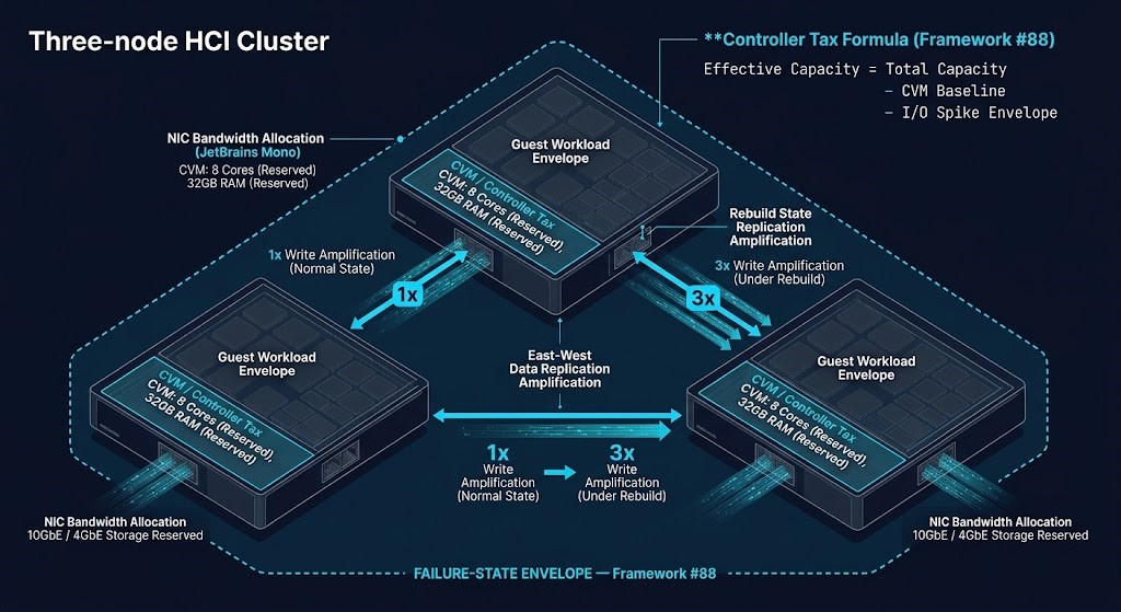
HCI architecture is not a steady-state design problem. The Failure-State Envelope is the resource boundary that determines cluster stability under rebuild, upgrade, and migration burst conditions.
SPECIALIZATION TRACK — HCI FAILURE-STATE ARCHITECTURE
- Track Discipline: The architectural discipline governing how compute, storage, and network converge within shared silicon and the Failure-State Envelope that convergence produces under rebuild events, rolling upgrades, and concurrent node degradation.
- Primary Architectural Tension: Convergence efficiency vs. failure-domain isolation — maximizing resource utilization against the replication amplification, controller contention, and rebuild traffic that the Failure-State Envelope generates when the cluster enters a degraded state.
- Architectural Boundary: Does not govern external storage or disaggregated compute architectures — those belong to the Storage Architecture and Compute Architecture Tracks respectively. HCI convergence governs only the shared-silicon model where storage, compute, and network occupy the same physical node boundary.
- Domain Path Relationship: Deepens Stages 2–4 of the Virtualization Architecture Path — Control Plane Architecture, Storage & Network Architecture, and Deterministic Operations — where convergence physics determine platform behavior under load but the Failure-State Envelope is not modeled at depth.
- Who This Track Is For: You’re sizing an HCI cluster for production, running post-migration AHV or vSAN operations, or encountering performance anomalies under node failure or upgrade windows that don’t trace back to application code — and you need the architectural framework to model what’s actually happening at the convergence boundary.
HCI architecture is the discipline governing how compute, storage, and network share physical silicon within a single fault domain — and what the Failure-State Envelope determines about cluster stability when that sharing is stressed by rebuilds, rolling upgrades, and migration bursts. Most teams discover the envelope at 2am during an upgrade window, not during the sizing exercise that preceded it. The cluster that passed pre-production validation at steady state is a different cluster when a node fails mid-upgrade and rebuild traffic begins flooding the east-west fabric — and the gap between those two conditions was never modeled because it wasn’t visible until the cluster entered it.
Specialization Tracks deepen specific architectural disciplines across multiple maturity stages without replacing the progression logic of the Domain Path itself. The Virtualization Architecture Path covers convergence at Stages 3 and 4 — Storage & Network Architecture and Deterministic Operations — at the breadth needed to understand platform behavior under normal conditions. Those stages introduce the controller tax, replication factors, and failure domain design as architectural concepts. They don’t resolve the controller tax calculus at cluster sizing depth, the replication amplification math under rebuild conditions, or the N+1 headroom requirements that the Failure-State Envelope makes non-negotiable in production. This Track provides that depth across five clusters.
>_ WHY THIS TRACK EXISTS
HCI architecture hides its highest failure risk inside the convergence model itself — the shared silicon boundary where storage controller demands and guest workload demands compete for the same CPU, memory, and network without external arbitration. When that boundary isn’t modeled as a Failure-State Envelope before sizing, clusters that pass pre-production validation fail under rebuild events, rolling upgrades, and migration bursts because they were sized against steady-state utilization rather than the resource condition the cluster enters during concurrent degradation. The Virtualization Domain Path covers convergence at Stages 2–4 at the breadth needed for platform selection and basic cluster design — it doesn’t resolve the controller tax modeling, replication amplification calculus, or N+1 headroom requirements against the Failure-State Envelope that production HCI operations require. This Track provides that architectural depth across five clusters: convergence physics, distributed resiliency, Failure-State Envelope modeling, platform implementation through the convergence lens, and governance portability as HCI clusters accumulate operational gravity over time.
NAMED FRAMEWORK — #88 FAILURE-STATE ENVELOPE
The Failure-State Envelope is the operational resource boundary required for an HCI cluster to remain deterministic during rebuilds, rolling maintenance, replication amplification, and concurrent node degradation — not merely during steady-state production. It unifies controller tax, rebuild amplification, N+1 headroom, upgrade window buffer, migration burst capacity, and replication traffic into a single sizing model. The Failure-State Envelope is the architectural condition that separates a cluster sized for production from one sized for production under failure.
WHAT THIS TRACK IS NOT
01 — NOT NUTANIX OR VSAN PRODUCT TRAINING
This Track covers the convergence physics and Failure-State Envelope mechanics that apply across all HCI platforms — the architectural problem, not the vendor implementation.
02 — NOT A CLUSTER DEPLOYMENT GUIDE
This Track addresses architectural tradeoffs, failure-state conditions, and sizing principles — not step-by-step deployment procedures for any specific platform.
03 — NOT THE STORAGE ARCHITECTURE TRACK
HCI convergence governs how storage and compute share silicon within a node boundary — the Storage Architecture Track governs how storage systems are designed as standalone tiers separate from compute. The distinction matters: convergence problems surface as controller contention; disaggregated storage problems surface as fabric latency.
04 — NOT PERFORMANCE BENCHMARKING
This Track covers the architectural conditions that determine Failure-State Envelope boundaries — the structural reasons clusters behave the way they do under degradation. Synthetic benchmark methodology and vendor performance claims are out of scope.
HCI FAILURE-STATE ARCHITECTURE — READING SCOPE
| Scope | Coverage | Estimated Time |
|---|---|---|
| Core Reading Sequence | Clusters 01–03 — convergence physics, distributed resiliency, and Failure-State Envelope modeling: the mechanical foundation of HCI sizing and operational decision-making | ~3–4 hr |
| Full Track | All five clusters — full architectural depth including platform implementation through the convergence lens and governance portability as HCI clusters accumulate operational gravity | ~5–7 hr |
>_ WHERE TO ENTER THIS TRACK
Start at Cluster 01 if you are planning an HCI deployment, evaluating HCI as a VMware exit destination, or migrating from a traditional three-tier architecture. Cluster 01 establishes the convergence physics that most platform evaluations skip — the reason clusters that size correctly for steady state fail under the conditions that inevitably arrive in production.
You can likely skip to Cluster 03 if all of the following apply:
- You have already run HCI in production and understand controller tax behavior under normal operating conditions
- You are specifically modeling upgrade windows, N+1 headroom, or rebuild amplification for an active sizing or capacity decision
- You are post-migration and managing Day 2 AHV or vSAN operations where the performance anomalies are surfacing under load events rather than baseline operation
If any of those require translation work, start at Cluster 01. The Failure-State Envelope modeling in Cluster 03 depends on the convergence physics established in Clusters 01 and 02 — entering Cluster 03 without that foundation produces sizing decisions that look correct but don’t account for the conditions that make them inadequate.
>_ READING SEQUENCE
Each cluster below is organized by architectural problem. Every cluster answers: what becomes architecturally unstable if this discipline is misunderstood?
CLUSTER 01 — CONVERGENCE PHYSICS: SHARED SILICON & CONTROLLER TAX — ENTRY POINT
Where Steady State and the Failure-State Envelope First Diverge
HCI convergence places the storage controller on the same physical silicon as the guest workload — a design choice that produces the Controller Tax: the CPU, memory, and NIC capacity consumed by the storage fabric before a single guest vCPU executes. The cluster that looks healthy at 70% utilization in vCenter is running at effective capacity when the controller tax envelope and I/O spike buffer are accounted for. This cluster establishes the shared silicon physics that every subsequent cluster in this Track depends on — and that most HCI sizing exercises skip.
The CVM Tax, shared CPU arbitration, and the resource envelope that separates safe cluster headroom from production risk — the Controller Tax defined at architectural depth.
The Controller Tax: Modeling Hyperconverged Resource Contention →Scheduler semantics, NUMA locality, and storage path changes when workloads move from ESXi to AHV — execution physics translation before the first production VM moves.
Beyond the VMDK: Translating Execution Physics from ESXi to AHV →CPU wait time, memory ballooning mechanics, and resource pooling physics in dense HCI clusters — how overcommitment assumptions from three-tier environments produce contention surprises in convergence models.
Resource Pooling Physics: CPU Wait & Memory Ballooning in Dense Clusters →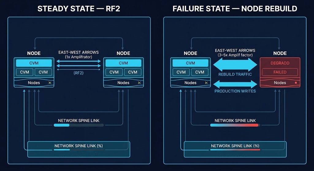
Every write event triggers coordinated east-west replication. Under node failure or upgrade, that traffic amplifies — and the fabric that looked adequate at steady state becomes the primary constraint.
CLUSTER 02 — DISTRIBUTED RESILIENCY: EAST-WEST AMPLIFICATION & REBUILD PHYSICS
Replication Amplification as a First-Order Architectural Constraint
Distributed resiliency changes failure behavior from isolated component loss into coordinated east-west recovery amplification. Replication traffic, rebuild sequencing, and latency propagation become first-order architectural constraints rather than background infrastructure mechanics. The east-west fabric that handles baseline replication at RF2 is a different fabric during a node failure when rebuild traffic, replication recovery, and normal production writes all compete for the same spine links simultaneously. This cluster maps the amplification mechanics that Cluster 03’s Failure-State Envelope sizing must account for.
Microburst behavior, synchronous replication latency, and the physical consequences of disconnected cloud operations — how east-west traffic patterns behave at metro scale under failure conditions.
The Physics of Disconnected Cloud: Modeling Microbursts & Metro Risk →Why east-west fabric determinism is the missing layer in HCI resilience planning — how latency jitter and non-deterministic traffic behavior undermine replication guarantees before a node failure occurs.
Deterministic Networking: The Missing Layer in AI-Ready Infrastructure →How infrastructure degrades through ordered failure stages rather than sudden collapse — and why the degradation sequence determines whether a cluster recovers deterministically or compounds into full outage.
The Degradation Ladder →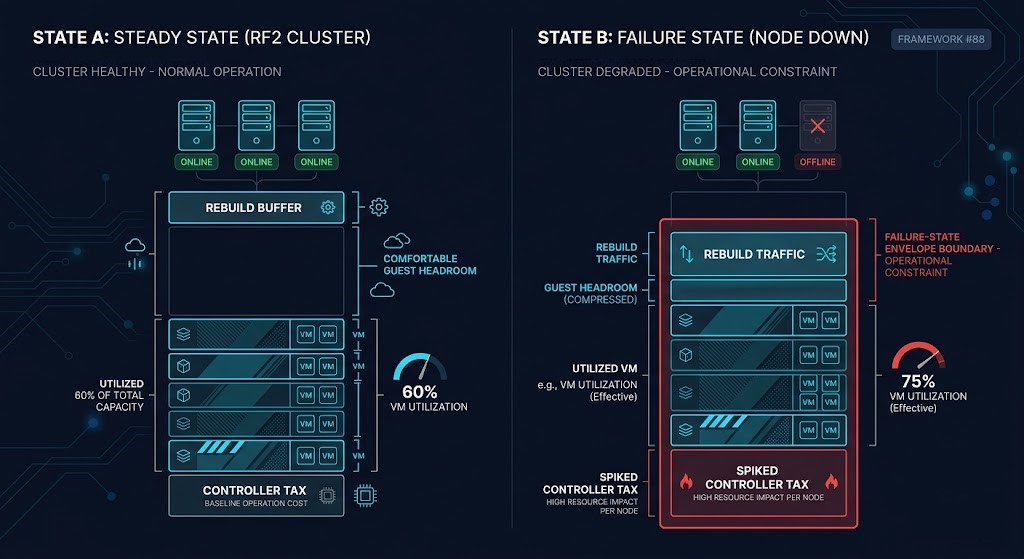
The cluster that passes production validation at steady state is a different cluster during a node failure. The Failure-State Envelope is the gap between those two resource conditions — and it must be modeled before sizing, not discovered after.
CLUSTER 03 — FAILURE-STATE ENVELOPE MODELING: N+1, UPGRADE PHYSICS & MIGRATION BURSTS
Sizing for the Condition the Cluster Inevitably Enters
Most HCI clusters are sized against steady-state utilization rather than the Failure-State Envelope (Framework #88) — the resource condition the cluster enters during rebuilds, rolling upgrades, replication recovery, and concurrent node degradation. Sizing for steady state produces a cluster that performs correctly until it doesn’t — then performs incorrectly at exactly the moment correctness is most critical. This cluster maps the architectural mechanics of the Failure-State Envelope and the three production scenarios where it determines whether the cluster survives or compounds into cascading instability.
Why every rolling upgrade is a controlled failure event — AOS, AHV, and Foundation upgrade dependency chains, CVM availability windows, and the N+1 headroom model that determines whether upgrades complete cleanly or trigger the Failure-State Envelope.
Upgrade Physics: Designing for Rolling Maintenance in AHV →The three I/O collision events that produce migration stutter in high-throughput cutover windows — how storage replication saturation triggers the same resource contention as a node failure during a migration burst.
Migration Stutter: Handling High-I/O Cutovers Without Data Loss →The operational model differences that surface during the post-migration normalization window — what changes in AHV Day 2 operations, where VMware operational assumptions break, and how the Failure-State Envelope behaves differently than vSAN under equivalent load.
Nutanix AHV Operations: What’s Different After Migration →CLUSTER 04 — PLATFORM IMPLEMENTATION: CONVERGENCE MODELS UNDER LOAD
How Different Convergence Architectures Express Failure-State Behavior
Platform implementation analysis at Track depth is not feature comparison — it is the study of how different convergence models express controller arbitration, replication behavior, failure recovery, and governance constraints under load. The question is not which platform has a better benchmark. It is which platform’s convergence model is compatible with your Failure-State Envelope and governance requirements. Teams that approach HCI platform selection as a feature matrix exercise select platforms they can buy but cannot size correctly — the Failure-State Envelope only becomes visible when you model the convergence architecture, not the specification sheet.
Post-Broadcom decision framework through the convergence lens — cost predictability, control plane ownership, migration physics, and exit cost architecture as the four axes that actually determine the VMware vs Nutanix evaluation.
Nutanix vs VMware: The Post-Broadcom Decision Framework →The operational physics, governance capability gaps, and support model constraints that differentiate Proxmox, Nutanix, and VMware at enterprise scale — constraint analysis rather than feature comparison.
Proxmox vs Nutanix vs VMware: The Post-Broadcom Constraints No One Explains →How AHV and Proxmox/Ceph express different convergence models under VMware evacuation load — I/O reality vs. vendor performance claims when the migration burst enters the Failure-State Envelope of the destination cluster.
Performance Modeling the VMware Evacuation: AHV vs Ceph I/O Reality →
Platform gravity is not visible at procurement. It accumulates through backup integration, lifecycle tooling, observability calibration, and operational muscle memory — until the governance cost of exit exceeds the original licensing cost that triggered the migration.
CLUSTER 05 — GOVERNANCE PORTABILITY & PLATFORM SOVEREIGNTY
When HCI Governance Dependencies Become Architectural Commitments
HCI platforms are not merely infrastructure stacks — they are governance systems with embedded operational assumptions, lifecycle tooling, replication models, and policy authority surfaces. Sovereignty begins when those governance dependencies become portable rather than vendor-bound. This cluster covers why HCI clusters become operationally sticky over time, how that stickiness accumulates through backup integration, observability calibration, and operational muscle memory, and what it takes to make platform governance portable enough to exit intentionally rather than by force. The Fragmented Control Plane that emerges during VMware coexistence is the same governance architecture problem that HCI platform gravity creates at a slower cadence — both require deliberate architectural design to manage. A third case sits beside platform gravity: the cluster that never exits at all, where the storage boundary convergence collapsed starts reappearing underneath the platform you kept — a seam-ownership question, not an exit-cost one.
How dual-platform HCI operations produce the Fragmented Control Plane — governance fragmentation, tooling divergence, and the cost surface of managing two convergence architectures simultaneously during VMware coexistence.
The VMware Exit Has Entered the Coexistence Era →The architectural framework for modeling, measuring, and closing the Governance Portability Gap — Framework #86 at full depth. What portability requires at the policy, lifecycle tooling, observability, and operational continuity layer.
Governance Portability Architecture [PLANNED] →The third case beside platform gravity and coexistence: you stay on the platform, and the storage boundary convergence collapsed starts separating underneath you. Who owns the seam that separation creates.
Hyperconverged Infrastructure Won the Battle — Then Created the Next Problem →>_ CROSS-TRACK DEPENDENCIES
Tracks share foundational mechanics across disciplines. Understanding which Tracks compound with this one prevents siloed architectural analysis.
| Depends On | Dependency Direction | Why It Matters |
|---|---|---|
| Virtualization Architecture Path | Domain Path Parent | Stages 2–4 establish the convergence baseline this Track extends — Control Plane Architecture, Storage & Network Architecture, and Deterministic Operations introduce the concepts this Track models at production depth |
| Migration Strategy Track | Bidirectional | HCI is the primary VMware exit destination — migration physics and Failure-State Envelope sizing are tightly coupled during the transition window; the Migration Strategy Track defines the governance requirements the destination HCI platform must satisfy |
| Storage Architecture Track | Bidirectional | HCI convergence shares silicon with distributed storage; when the convergence model requires disaggregated storage tiers alongside HCI, Storage Architecture governs those tiers — both Tracks shape the storage boundary decision |
| Networking Architecture Track | Upstream Constraint | East-west fabric design is a direct Failure-State Envelope dependency — insufficient lateral bandwidth collapses the envelope during rebuilds and rolling upgrades; Networking Architecture provides the fabric design foundation Cluster 02 depends on |
| Performance Modeling Track | Downstream Consumer | Failure-State Envelope sizing feeds directly into performance modeling methodology — the envelope defines the resource boundary that performance models must account for across all operational states, not just steady state |
| Data Protection & Resiliency Path | Downstream Consumer | Backup and recovery architecture against HCI convergence models inherits the Failure-State Envelope directly — rebuild amplification, backup window scheduling, and recovery traffic modeling are governed by the convergence physics this Track defines |
>_ ARCHITECT’S READING NOTES
THE CONVERGENCE TRAP — THREE SIZING ERRORS THIS TRACK CLOSES
The three most common HCI sizing errors each map to a specific cluster. Error 1 — ignoring the controller tax: treating the published CPU and memory specs as fully available for guest workloads rather than netting the controller baseline before any VM allocation. Cluster 01 addresses this. Error 2 — sizing for baseline replication traffic: modeling east-west fabric against normal RF2 writes rather than against the amplified traffic of a simultaneous rebuild and production write load. Cluster 02 addresses this. Error 3 — sizing for steady-state utilization: planning headroom against average VM utilization rather than against the Failure-State Envelope that determines whether the cluster survives a node failure mid-upgrade window. Cluster 03 addresses this. All three errors produce clusters that size correctly on paper and fail in production at the worst possible moment.
THE REBUILD WINDOW — WHY UPGRADE PHYSICS AND NODE FAILURE SHARE THE SAME MATH
A rolling upgrade is a controlled failure event. The resource math for a node entering maintenance mode during an upgrade is identical to the resource math for a node failure — in both cases, the surviving nodes absorb the workload, rebuild traffic floods the east-west fabric, and the cluster enters the Failure-State Envelope for the duration. The only difference is that an upgrade is scheduled and a failure is not. This means the N+1 headroom model applies identically to both scenarios. Clusters sized for upgrade windows without modeling the simultaneous controller contention and rebuild traffic are sized for a scenario that never actually occurs in production — and will enter the Failure-State Envelope exactly when the upgrade window opens.
STEADY STATE VS FAILURE STATE — WHAT ARCHITECTS ACTUALLY SIZE FOR
| Operational Mode | What Architects Usually Size For | What Actually Determines Stability |
|---|---|---|
| Steady State | Average VM utilization | Predictable runtime behavior with controller tax accounted for |
| Node Failure | Remaining host capacity after node loss | Rebuild amplification across east-west fabric + controller spike on surviving nodes |
| Rolling Upgrade | Maintenance window duration | Simultaneous controller contention + temporarily reduced replication factor during evacuation |
| Migration Burst | VM mobility throughput targets | Storage replication saturation on destination cluster entering Failure-State Envelope |
| DR Recovery | VM restart count at recovery site | East-west recovery traffic profile against recovery cluster Failure-State Envelope |
PLATFORM GRAVITY — WHY HCI CLUSTERS BECOME OPERATIONALLY STICKY
Platform gravity is not visible at procurement. It accumulates through six channels that each independently increase the governance cost of platform exit: backup integration calibrated to the convergence model, lifecycle tooling tuned to the upgrade cadence, observability thresholds built against the platform’s specific failure signatures, replication mechanics encoded in DR runbooks, operational muscle memory accumulated through production incidents, and vendor support relationships built around platform-specific escalation paths. None of these is an argument against committing to HCI. All of them are arguments for treating the platform selection decision as a governance commitment rather than a procurement event — and for building sovereignty into the operational model before gravity makes exit prohibitively expensive. Cluster 04 covers the platform constraint analysis. Cluster 05 covers what portable governance of those commitments actually requires. The Migration Strategy Track covers what happens when governance portability isn’t designed in from the start. The Sovereign Virtualization Architecture stage is where those commitments resolve at the strategic architecture level.
>_ TRACK GRADUATES CAN NOW
HCI architecture at Track depth means the convergence model is no longer opaque — the Failure-State Envelope, controller tax, and replication amplification are modelable before the first node order. The distinction between a cluster sized for steady state and one sized for the degradation condition it will inevitably enter is now a first-class design input, not a post-incident discovery. Platform selection is now a governance commitment analysis, not a feature comparison exercise.
- Model the Failure-State Envelope before cluster sizing — controller tax, rebuild amplification, N+1 headroom, and upgrade window buffer as a unified resource boundary rather than independent sizing parameters
- Calculate east-west fabric capacity against replication amplification and rebuild burst profiles, not baseline workload traffic — and validate that the fabric holds across all five operational modes in the steady-state vs failure-state table
- Evaluate HCI platform implementation tradeoffs through the convergence physics lens — how each platform’s controller model expresses failure recovery and governance constraints, not which has the more favorable benchmark
- Distinguish governance portability from feature availability — assess whether HCI lifecycle tooling, replication models, and policy authority surfaces are portable before Platform Gravity makes exit architecturally expensive
- Apply HCI Failure-State Envelope constraints to adjacent architecture decisions — data protection recovery traffic, AI inference cluster sizing, and Kubernetes node density all inherit the same convergence physics this Track governs, making the Failure-State Envelope model directly reusable across disciplines
>_ WHERE DO YOU GO FROM HERE
YOUR HCI SIZING MATH IS PROBABLY MISSING THE FAILURE-STATE ENVELOPE
If your cluster is sized against steady-state utilization rather than the Failure-State Envelope, the Migration Readiness Assessment surfaces the controller tax gap, rebuild amplification exposure, and N+1 headroom deficit before they become a production incident.
VMware Migration Readiness Assessment
A structured architectural review of your HCI target environment — controller tax baseline, Failure-State Envelope headroom, and migration burst capacity before the first production workload moves.
- > Failure-State Envelope baseline — controller tax + N+1 headroom
- > East-west rebuild amplification profile
- > Upgrade window buffer vs. concurrent controller contention
- > Platform governance portability assessment
Architecture Playbooks. Field-Tested Blueprints.
Field-tested blueprints for HCI architecture — convergence models, Failure-State Envelope frameworks, and platform decision guides for architects sizing and operating enterprise HCI clusters.
- > HCI convergence architecture and controller tax modeling
- > Failure-State Envelope sizing and N+1 headroom framework
- > Platform decision constraint analysis — Nutanix, vSAN, Proxmox
- > Post-migration AHV Day 2 operations and governance normalization
Zero spam. Unsubscribe anytime.
>_ FREQUENTLY ASKED QUESTIONS
Q: What is HCI architecture and why does it require a Failure-State Envelope rather than steady-state sizing?
A: HCI architecture is the discipline governing how compute, storage, and network share physical silicon within a single fault domain — a convergence model that produces significant operational efficiencies at steady state and significant amplification risks under degradation. The Failure-State Envelope is required because the resource boundary that matters for cluster stability isn’t the utilization level during normal operation; it’s the resource condition the cluster enters during rebuilds, rolling upgrades, replication recovery, and concurrent node degradation. A cluster sized for steady-state utilization will perform correctly until it enters the Failure-State Envelope — which it will do during every upgrade window, every node failure, and every high-I/O migration burst. Sizing for the envelope rather than steady state is the difference between a cluster that survives its first production incident and one that compounds it.
Q: What is the Failure-State Envelope and what does it unify in HCI cluster design?
A: HCI cluster to remain deterministic during rebuilds, rolling maintenance, replication amplification, and concurrent node degradation — not merely during steady-state production. It unifies six distinct resource demands into a single sizing model: controller tax (the CPU and memory baseline consumed by the storage controller before any guest workload allocates resources), rebuild amplification (the additional east-west traffic generated when a node fails and data protection rebuilds to the surviving nodes), N+1 headroom (the spare capacity required to absorb a node loss without triggering cascading contention), upgrade window buffer (the additional controller contention during rolling node evacuations), migration burst capacity (the replication saturation created when large workloads move onto the cluster), and replication traffic (the baseline east-west load from the cluster’s replication factor under normal production writes). Before Framework #88, these were typically sized independently. The Failure-State Envelope treats them as a unified boundary — because they all occur simultaneously during the conditions that determine whether the cluster survives.
Q: What is the controller tax and when does it become a production problem?
A: The controller tax is the CPU, memory, and network bandwidth consumed by the HCI storage controller — the CVM in Nutanix AOS, the kernel-integrated storage service in vSAN — before any guest workload receives resources. In Nutanix, the CVM typically consumes a baseline of 4–6 vCPUs and 16–24GB RAM under normal conditions, with additional CPU consumption during I/O-intensive operations. In a correctly sized cluster, the controller tax is accounted for before guest headroom is calculated, and the remaining capacity is sufficient for both steady-state guest workloads and the I/O spike envelope the controller experiences under rebuild conditions. The controller tax becomes a production problem in three scenarios: when clusters are sized without netting the controller baseline from available capacity, leaving less guest headroom than projected; when I/O spike envelopes aren’t modeled, causing controller CPU demand to spike into guest CPU during storage-intensive events; and when N+1 headroom is calculated against total node capacity rather than effective capacity after the controller tax, underestimating the surviving capacity available after a node failure.
Q: What is the difference between east-west replication amplification and standard network utilization in HCI?
A: Standard east-west network utilization in an HCI cluster includes normal RF2 or RF3 write traffic — the coordinated writes that distribute data across nodes to maintain the replication factor. That traffic is predictable, continuous, and sized for during normal capacity planning. East-west replication amplification is the additional traffic generated when the cluster enters a degraded state — specifically when a node fails and the cluster must rebuild data protection across the surviving nodes. During a rebuild, every block that was on the failed node must be re-replicated across the remaining nodes simultaneously while normal production writes continue. The rebuild traffic is additive to baseline replication traffic and can multiply east-west load by 3–5x during active rebuild windows. The east-west fabric that handles baseline RF2 replication comfortably will saturate during a rebuild if it wasn’t sized against the amplified load. This is why Cluster 02 of this Track treats replication amplification as a first-order architectural constraint rather than a background consideration — it determines whether the fabric holds during the conditions that define cluster resilience.
Q: When should an architect choose HCI over disaggregated compute and storage, and what governance commitment does that choice imply?
A: HCI is architecturally appropriate when workload density, operational simplicity, and integrated resiliency justify the convergence model’s tradeoffs — specifically when the controller tax headroom cost is acceptable relative to the management surface reduction, and when the replication amplification behavior under failure is acceptable relative to the operational simplicity of eliminating a separate storage fabric. The governance commitment that choice implies is what this Track’s Cluster 05 addresses: HCI clusters accumulate Platform Gravity through backup integration, lifecycle tooling, observability calibration, and operational muscle memory. That gravity increases the governance cost of future platform exit in ways that aren’t visible at procurement. The architect who treats HCI selection as a purely technical decision without modeling the governance commitment will eventually face an exit decision where the accumulated gravity makes options more constrained than expected. The correct framing is: choose HCI when the convergence model’s operational benefits justify both the Failure-State Envelope sizing requirements and the governance commitment that Platform Gravity implies.
>_ RELATED SYSTEMS
The VMware Exit toolkit hub — HCI migration advisor, licensing cost modeling, VMware renewal estimator, and operational tools aligned to the convergence physics and Failure-State Envelope requirements this Track defines.
Open Workbench →Model your VMware-to-HCI migration path — workload placement, platform fit, and migration sequencing across AHV, Proxmox, and KVM targets. Surfaces NUMA alignment, snapshot depth, and CPU headroom before the first node order.
Open Tool →The strategic architecture maturity stage where HCI platform governance decisions resolve — governance portability, control plane replaceability, and operational sovereignty are the architectural conditions Stage 5 defines.
Open Stage →Backup and recovery architecture inherits the Failure-State Envelope directly — rebuild amplification windows, backup job scheduling against HCI replication traffic, and DR recovery traffic modeling all operate inside the convergence physics this Track defines.
Open Path →Authoritative reference on AOS distributed storage fabric, CVM I/O path, replication factor mechanics, and data locality — the primary engineering documentation behind the convergence physics this Track covers.
External Reference →Broadcom’s canonical vSAN architecture documentation — storage policy design, failure domain configuration, and capacity planning methodology for the vSAN convergence model covered in Cluster 04 of this Track.
External Reference →