STORAGE & DATA PIPELINE ARCHITECTURE
Compute starvation starts at the data layer — not the accelerator layer.
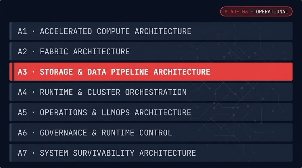
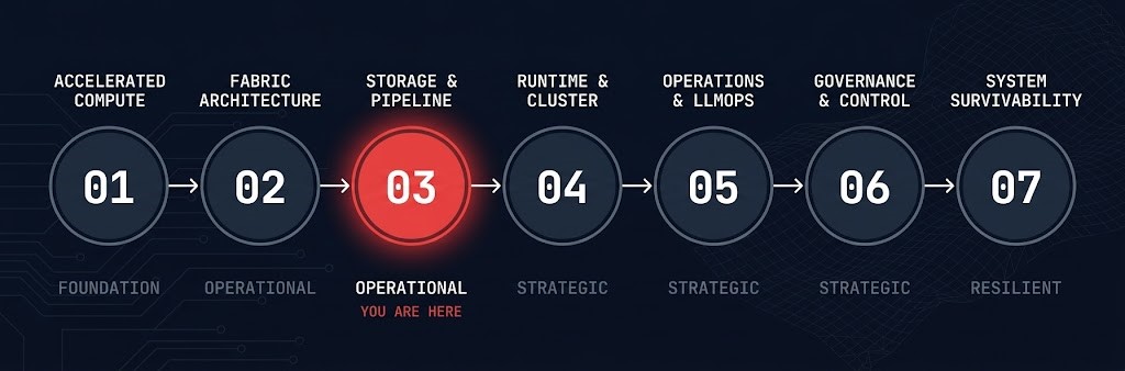
MATURITY POSITION — AI INFRASTRUCTURE STAGE 03 OF 07
- Current Stage: Operational — Maturity Stage 03 of 07
- Primary Architectural Concern: Data locality, pipeline latency, and checkpoint architecture as first-class compute dependencies — how storage design determines whether execution runs or stalls
- Primary Failure Mode: Data-Blind Architecture — sizing accelerators, fabric, and schedulers independently while assuming data delivery will scale automatically with compute demand
- Stage Outcome: Ability to identify the Data Availability Boundary and design storage, checkpoint, and pipeline architectures that maintain execution continuity under scale
- Next Stage: Runtime & Cluster Orchestration → Runtime & Cluster Orchestration
Storage data pipeline architecture is the stage where AI infrastructure decisions stop being about storage administration and start being about execution continuity. The assumption that underlies most AI infrastructure failures at this layer is that storage is a background concern — a substrate that scales automatically as compute and fabric scale. It does not. Data locality, pipeline latency, and checkpoint design determine whether accelerators run or stall, and they do so independently of how much compute capacity is provisioned above them.
The articles in this stage treat storage as a constraint layer, not a service layer. Each one addresses a specific mechanism by which data delivery fails to keep pace with execution — whether through locality collapse, throughput saturation, checkpoint amplification, or the durability tradeoffs that silently destroy throughput at scale. Understanding these mechanisms is what separates architects who size storage correctly from architects who discover the storage wall after procurement is complete.
WHY THIS STAGE EXISTS — DATA-BLIND ARCHITECTURE
Most AI infrastructure failures at the storage layer share a common origin: the system was designed with Data-Blind Architecture. Accelerators are sized against benchmark throughput. Fabric is sized against GPU count. Schedulers are configured against job arrival rates. Storage is treated as a background service that will scale to meet whatever demand the compute layer generates.
The symptoms are consistent: idle accelerators during training runs, checkpoint storms that collapse throughput under scale, storage walls encountered during model expansion, and locality failures that appear only under production inference load. None of these are compute problems. They are data delivery problems that compute procurement cannot fix.
This stage exists to make the data layer visible before procurement decisions are made — and to give architects the framework language to diagnose data delivery failures before they are misattributed to insufficient compute.
Stage Anchor Question
What constrains data movement?
Data movement is constrained by locality, throughput, checkpoint architecture, and storage durability choices. Once the Data Availability Boundary (#117) is crossed — the point at which data delivery becomes the limiting factor on execution regardless of available compute capacity — adding accelerators no longer improves execution. The boundary must be identified before compute is procured, not after it stalls.
What This Stage Is Not
Not storage administration. This stage does not cover backup schedules, capacity planning dashboards, or vendor management. It covers storage as an execution constraint — how architectural decisions at the storage layer propagate into accelerator utilization and pipeline throughput.
Not a vendor selection guide. NVMe, Ceph, ZFS, and NVMe-oF appear throughout this stage as architectural options with specific tradeoffs under specific workload conditions — not as products to be ranked or recommended independently of the environment they serve.
Not the durability layer. Data Protection architecture — backup, immutability, ransomware recovery, and DR topology — lives in the Data Protection & Resiliency path. This stage covers durability decisions only where they create direct throughput consequences for execution: erasure coding overhead, replication lag under checkpoint load, and consistency requirements that affect pipeline sequencing.
Not a substitute for Stage 02. Fabric Architecture (A2) establishes the east-west bandwidth constraints and interconnect physics that bound what storage can deliver to compute. This stage assumes that foundation. Architects who skip A2 and proceed here will encounter storage wall analyses that reference fabric constraints they haven’t modeled.
>_ Estimated Reading Depth
| Format | Count | Estimated Time | Notes |
|---|---|---|---|
| Architecture articles | 7 | ~3 hrs | Core reading sequence — all four clusters |
| Interactive tool | 1 | ~30 min | AI Ceph Throughput Calculator — apply storage wall analysis to your cluster |
| Total stage depth | 8 | ~3.5–4 hrs | Complete before proceeding to A4 Runtime & Cluster Orchestration |
>_ Where to Enter This Stage
This stage is the right entry point if you are designing or evaluating AI infrastructure where execution continuity — not peak benchmark throughput — is the architectural goal. Specifically, enter here if:
– Accelerators in your cluster show idle time that cannot be explained by scheduler configuration or job queue depth
– You are making checkpoint frequency decisions based on checkpoint duration alone, without accounting for throughput disruption at scale
– Your storage architecture was designed to match compute capacity rather than to bound the Data Availability Boundary first
– You are evaluating distributed versus local storage for AI training and have not yet modeled the consistency and throughput tradeoffs under checkpoint load
>_ Architecture Maturity Position
| Stage | Name | Maturity Level | Stage Question |
|---|---|---|---|
| A1 | Accelerated Compute Architecture | Foundation | What does an accelerator actually execute? |
| A2 | Fabric Architecture | Operational | What moves data between accelerators? |
| A3 ← YOU ARE HERE | Storage & Data Pipeline Architecture | Operational | What constrains data movement? |
| A4 | Runtime & Cluster Orchestration | Strategic | How are workloads admitted, placed, and isolated? |
| A5 | Operations & LLMOps Architecture | Strategic | How is model lifecycle governed operationally? |
| A6 | Governance & Runtime Control | Strategic | Who owns runtime authority? |
| A7 | System Survivability Architecture | Resilient | What degrades gracefully and what collapses? |
>_ Stage Reading Sequence
The sequence below is organized by architectural problem cluster. Each cluster answers: what becomes architecturally unstable if this discipline is misunderstood?
Architectural question: Where must data live for execution to remain viable?
Where must data live for execution to remain viable?
Locality is the first constraint in the data pipeline. Before throughput, before erasure coding, before checkpoint frequency — the question is whether data can reach compute fast enough to prevent starvation. These two articles cover the distributed vs. local storage decision in AI training environments and map the storage wall that teams encounter when locality assumptions fail under scale.
Architectural question: What happens when data delivery cannot keep pace with execution?
What happens when data delivery cannot keep pace with execution?
Idle accelerators are rarely a compute problem. These two articles diagnose GPU idle time as a data pipeline starvation signal — and map the cloud waste patterns that emerge when storage constraints are misread as capacity shortfalls. Both are foundational to understanding the Data Availability Boundary as it manifests in production environments.
>_ Storage & Data Pipeline Architecture Failure Patterns
Architectural question: How much performance are you willing to exchange for recoverability?
How much performance are you willing to exchange for recoverability?
Durability choices are throughput choices. Erasure coding, replication factors, and consistency levels all carry execution cost — and that cost compounds under checkpoint load at scale. These two articles cover the SLA determinism problem in AI storage and the economics of inference steady state where storage cost becomes a persistent operational constraint rather than a one-time infrastructure decision.
Architectural question: How do storage locality decisions propagate into workload placement constraints?
How do storage locality decisions propagate into workload placement constraints?
Placement decisions are constrained by storage locality. Where data lives determines where workloads can run efficiently — and those constraints become architectural commitments, not runtime options. This cluster bridges A3 into A4 by establishing that the scheduler inherits the placement constraints set at the storage layer. What the Runtime & Cluster Orchestration stage adds is the admission and isolation logic that operates within the locality constraints established here.
>_ Stage Graduates Can Now
Completing this stage establishes storage and data pipeline architecture as a first-class constraint in AI infrastructure design. What changed architecturally is the ability to identify the Data Availability Boundary before it becomes an execution bottleneck — and to trace idle compute back to data delivery failures rather than scheduler or capacity shortfalls. What Strategic maturity adds at A4 is the orchestration layer that operates within the placement and locality constraints this stage established.
- Identify the Data Availability Boundary before compute procurement decisions are made
- Determine when local storage outperforms distributed storage despite reduced durability, under specific AI workload conditions
- Design checkpoint strategies that minimize throughput disruption under scale by modeling checkpoint amplification before setting frequency
- Evaluate RAID, erasure coding, and replication against execution requirements rather than storage utilization metrics
- Diagnose compute starvation caused by data delivery constraints before modifying scheduler policies — the upstream boundary that A4 Runtime & Cluster Orchestration inherits.
The Runtime & Cluster Orchestration stage picks up where A3 closes — translating the placement constraints and locality commitments established here into admission policy, resource quota, and heterogeneous cluster governance.
No Specialization Tracks currently exist for the AI Infrastructure Architecture Path. Tracks are built after all seven maturity stages are live. This section will be populated as the path matures.
>_ Where Do You Go From Here
YOU’VE READ THE ARCHITECTURE.
NOW TEST WHETHER YOUR ENVIRONMENT HOLDS.
The Data Availability Boundary is a design constraint, not a monitoring alert. Identifying where it sits in your environment requires reviewing storage tiers, checkpoint architecture, and pipeline sequencing against your actual execution requirements — before the boundary becomes a stall.
Infrastructure Architecture Review
A structured review of your AI infrastructure against the architectural constraints this stage covers. Delivered as a written assessment with findings and remediation sequencing.
- > Data locality assessment against workload placement requirements
- > Storage architecture validation — tier design, backend selection, throughput modeling
- > Checkpoint strategy review — frequency, amplification risk, scale behavior
- > Data Availability Boundary analysis — where it sits and what crosses it first
Architecture Playbooks. Field-Tested Blueprints.
Field-tested blueprints for AI infrastructure storage and pipeline architecture — covering the failure modes this stage introduces.
- > Data Availability Boundary identification and remediation
- > Checkpoint architecture for training clusters at scale
- > Storage wall diagnosis and backend selection
- > Pipeline latency profiling for inference environments
Zero spam. Unsubscribe anytime.
>_ Frequently Asked Questions
Q: What is storage data pipeline architecture in the context of AI infrastructure?
A: Storage data pipeline architecture is the discipline of designing data movement and storage systems as execution constraints rather than background services. In AI infrastructure, this means treating data locality, pipeline latency, checkpoint frequency, and storage durability as first-class architectural decisions that directly determine whether accelerators run at capacity or stall waiting for data.
Q: What is the Data Availability Boundary?
A: The Data Availability Boundary is the point at which data delivery becomes the limiting factor on execution, regardless of available compute capacity. Once the boundary is crossed, adding more GPUs or expanding fabric does not improve execution — the constraint is in the data pipeline. Identifying where this boundary sits in a specific environment is the primary architectural goal of this stage.
Q: What is the Data Availability Boundary and why does adding GPUs not solve it?
A: The Data Availability Boundary is a data delivery constraint, not a compute constraint. When execution stalls because the storage layer cannot supply data fast enough to keep accelerators busy, the bottleneck is between the storage backend and the execution pipeline — not between jobs and available GPU capacity. Adding GPUs increases the demand on a pipeline that is already saturated. The correct response is to model and address the storage architecture: locality design, throughput ceiling, checkpoint amplification, and pipeline serialization points.
Q: What is Data-Blind Architecture?
A: Data-Blind Architecture is the failure mode where AI infrastructure is designed by sizing accelerators, fabric, and schedulers independently while assuming data delivery will scale automatically with compute demand. The symptoms — idle GPUs, checkpoint storms, storage wall encounters, and locality failures under production load — are often misattributed to compute or scheduler problems. This stage makes the data layer visible so that those decisions are made before procurement rather than diagnosed after stalls.
Q: How does this stage differ from the Data Protection & Resiliency path?
A: Storage architecture at A3 covers durability decisions only where they carry direct throughput consequences for execution: erasure coding overhead under checkpoint load, replication lag during training runs, and consistency requirements that affect pipeline sequencing. It does not cover backup architecture, immutability design, ransomware recovery, or DR topology — those belong to the Data Protection & Resiliency path, which governs recoverability rather than execution continuity.
Q: When should local NVMe storage be chosen over distributed Ceph storage for AI training?
A: Local NVMe outperforms distributed Ceph in environments where the training workload is dominated by random small reads, where checkpoint frequency is high, and where the network overhead of distributed access would exceed the throughput gain from shared capacity. Distributed Ceph becomes preferable when training data volumes exceed local capacity, when multiple jobs share a common dataset, or when checkpoint durability requirements justify the additional consistency overhead. The decision is not a vendor preference — it is a locality and throughput model specific to the workload.
Q: How does this stage connect to A2 Fabric Architecture and A4 Runtime & Cluster Orchestration?
A: A2 Fabric Architecture establishes the east-west bandwidth physics and interconnect constraints that bound what storage can deliver to compute — execution movement constraints become data movement constraints at the Data Availability Boundary. A3 takes those fabric constraints as given and models the storage layer within them. A4 Runtime & Cluster Orchestration then inherits the placement constraints established at A3 — where data lives determines where workloads can be efficiently scheduled, and the scheduler operates within those locality commitments.
>_ Related Systems
Execution movement constraints become data movement constraints at the Data Availability Boundary — the Execution Locality Boundary (#116) established at A2 bounds what storage can deliver to compute at A3.
Open Stage →The Provisioned-to-Executed Gap (#105) surfaces when accelerators stall — A3 provides the data pipeline explanation for why that gap exists and widens under load.
Open Stage →The full AI infrastructure pillar — storage and data pipeline architecture in the context of the wider AI infrastructure decision landscape.
Open Pillar →Storage architecture in virtualized environments — how the same distributed vs. local tradeoffs play out in HCI and post-VMware storage design.
Open Track →Ceph architecture reference — RADOS object storage, BlueStore backend, and the consistency and throughput model underlying the distributed storage options covered in Cluster 01.
Open Reference →NVMe over Fabrics architecture — the protocol layer that bridges local NVMe performance characteristics across a network fabric, relevant to the storage wall analysis in Cluster 01.
Open Reference →