

ENTERPRISE STORAGE ARCHITECTURE
The topology decision that locks in your latency budget, failure domain, and exit path simultaneously.
Enterprise storage architecture is decided at procurement time. That is the problem. The decision that determines your latency budget, your failure domain policy, and your exit path is made in a room with a vendor, under the illusion that you are making a capacity decision. You are not. You are committing to a topology — and topology is not reversible cheaply after the fact.
The storage layer is where more invisible technical debt accumulates than any other part of the infrastructure stack. Not because architects make uninformed decisions, but because the framing they work from is consistently wrong. The vendor sells capacity. The console shows IOPS. The procurement process models cost per terabyte. None of those frames surface the architectural consequence of the topology choice — where failure localizes, what survives loss, what rebuilds under pressure, and what the operational model costs to sustain over a three-to-five year horizon.
This page corrects the framing. It introduces the Storage Illusion — the set of beliefs that make poor topology decisions feel reasonable at the time. It defines the three architectural primitives that every storage decision resolves simultaneously. It presents the Rack2Cloud Storage Topology Model — the framework that maps topology classes against the variables that actually matter for architectural decisions. And it covers the failure modes, the IaC discipline, the AI storage inflection point, and the decision logic that should happen before any commitment hardens.
The Storage Illusion
Enterprise storage decisions go wrong for the same reason enterprise compute decisions go wrong: the framing that surrounds the decision is systematically incomplete. Vendors sell capacity. Consoles surface IOPS and throughput. Procurement processes model cost per terabyte. None of that framing exposes the architectural consequence of the topology choice — the failure domain it creates, the operational model it assumes, or the exit cost it builds in.
The table below names the five beliefs most responsible for poor storage architecture decisions. They are not naive beliefs. They are reasonable interpretations of the information that is typically visible at decision time. They collapse when the topology is tested under load, when a failure event exposes the actual failure domain, or when a migration forces a full inventory of what the storage layer actually owns.
| What Teams Believe | What It Actually Means |
|---|---|
| Storage is just capacity | Storage is topology, latency profile, and failure-domain policy |
| More IOPS fixes storage performance | IOPS without data path analysis is usually queue depth, not throughput |
| SDS is cheaper storage | SDS is storage whose operational burden has been moved into software |
| Cloud storage is elastic | Cloud storage is elastic until retrieval locality, rehydration latency, or egress cost matters |
| SAN is legacy | SAN is expensive — not obsolete |
The SDS line deserves to be stated without softening: SDS is not cheaper storage. It is storage whose operational burden has been moved into software. The management overhead of a hardware SAN does not disappear when you deploy Ceph. It is redistributed — into cluster operations, rebalancing management, failure recovery tooling, and the platform engineering capacity required to keep the management plane healthy. Organizations that chose SDS expecting to reduce operational cost and discovered instead that they had traded vendor support calls for internal engineering hours did not choose the wrong software. They chose the wrong operational model for the topology.
The cloud elasticity illusion is equally consequential in hybrid estates. Object storage is genuinely elastic at write time. At read time — specifically during large-scale restores, cross-region analytics queries, or backup rehydration events — the elasticity trades against latency floor, retrieval fees, and egress costs that were never in the original storage cost model. The storage decision that looked elastic at procurement becomes a cost event at recovery time.
DIAGNOSTIC QUESTION
“Can your team describe the operational model that owns your storage management plane — and staff it without the vendor on the call?”
What Enterprise Storage Architecture Actually Is
Storage architecture is not a capacity discipline. It is a failure-domain discipline. Every topology decision is simultaneously a decision about where failure localizes, what survives loss, what the system does under degraded conditions, and how long recovery takes. Those consequences are set at topology selection time. They do not change when you add capacity, upgrade firmware, or switch monitoring tools.
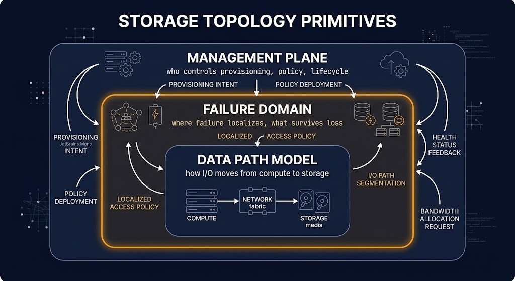
The corrected definition of enterprise storage architecture rests on three primitives. Every storage decision resolves all three, whether or not the decision-maker models them explicitly.
Data path model is how I/O moves from compute to persistent storage, and what happens at each hop. A local NVMe data path has no network traversal, no fabric dependency, and no shared queue. A SAN data path crosses a network fabric, shares queue resources with other initiators, and introduces protocol overhead at the host bus adapter. A software-defined storage data path routes I/O through a distributed system that adds consistency overhead, replication latency, and cluster coordination on every write. Each data path has a latency profile, a throughput ceiling, and a failure surface that is specific to its topology — and none of those characteristics change because a vendor’s datasheet quotes favorable benchmark numbers.
Failure domain is where failure localizes and what it takes with it. This is the variable that vendor documentation consistently underemphasizes and that architecture reviews consistently underweight. A node-local NVMe failure takes exactly one node’s data with it — nothing else in the environment is affected. An HCI cluster failure can degrade the entire storage pool because the failure domain is cluster-wide. A traditional SAN controller failure takes every host attached to that controller offline until failover completes. A cloud-native storage failure is opaque — the failure domain is provider-managed and not inspectable. Choosing a storage topology without explicitly modeling the failure domain is choosing a blast radius without meaning to.
Management plane is who controls provisioning, policy, and lifecycle — and what that control costs to exercise. A hardware SAN has a management plane that the vendor owns and that requires vendor engagement for significant operations. An SDS cluster has a management plane that the operator owns entirely — which means every provisioning decision, every rebalancing operation, every failure recovery event, and every upgrade is the operator’s operational responsibility. A cloud-native storage service has a management plane that the provider owns — which means operational simplicity at the cost of control, portability, and the ability to inspect what is actually happening inside the system.
Storage architecture is failure-domain design. The data path determines how fast you get to the failure. The management plane determines how quickly you can respond to it. The failure domain determines how much it takes with it when it happens.
The Rack2Cloud Storage Topology Model
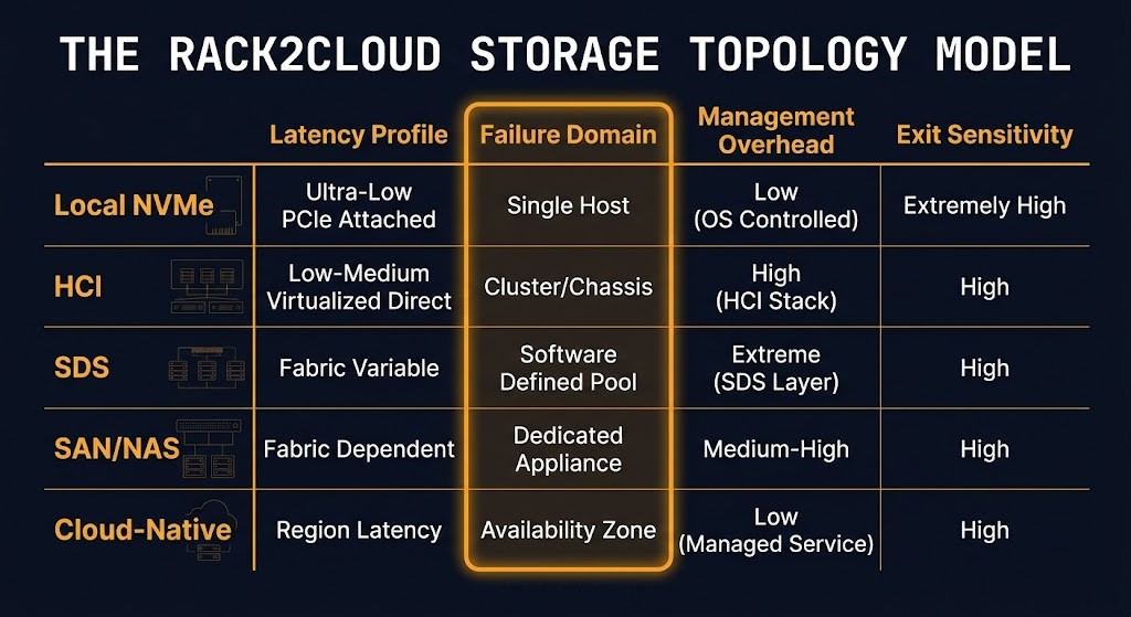
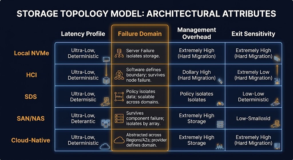
Every enterprise storage decision involves five topology classes and four architectural variables. The Rack2Cloud Storage Topology Model maps them explicitly — not to produce a vendor recommendation, but to make the tradeoff visible at design time rather than at failure time.
The four variables are latency profile, failure domain, management overhead, and exit sensitivity. The topology you choose resolves all four simultaneously. Most storage procurement conversations surface only the first — and sometimes the third when cost is the driver. The second and fourth are the variables that determine what actually happens when something goes wrong or when the environment needs to change.
| Topology | Latency Profile | Failure Domain | Management Overhead | Exit Sensitivity |
|---|---|---|---|---|
| Local NVMe / DAS | Sub-millisecond, deterministic | Node-local — failure is isolated | Minimal | High — data moves with compute |
| Hyperconverged (HCI) | Low, shared-pool | Cluster-wide — failure propagates | Low | Medium — platform-coupled |
| Software-Defined Storage (SDS) | Variable, policy-tunable | Policy-defined — operator-controlled | Medium–High | Low — portable if operated correctly |
| Traditional SAN/NAS | Predictable, hardware-dependent | Array-level — controller is a single point | High | High — vendor-locked |
| Cloud-Native Object/Block | Variable, provider floor | Provider-managed — opaque | Minimal | High — egress cost + API dependency |
The failure domain column is the column that vendors never highlight. It is also the column that determines the blast radius of every failure event the environment will experience over the life of the storage investment. An HCI cluster where the failure domain is cluster-wide means that a cluster-level failure event — a bad firmware update, a split-brain condition, a runaway rebalancing operation — affects every workload in the pool simultaneously. A local NVMe topology where the failure domain is node-local means a node failure is precisely scoped. The recovery operation is proportionally sized. The blast radius is contained.
The exit sensitivity column deserves equal weight. Local NVMe has high exit sensitivity not because the hardware is difficult to replace, but because the data is physically co-located with the compute — moving the workload means moving the data, which introduces a migration event with its own downtime window and operational risk. Cloud-native storage has high exit sensitivity not because the data is hard to extract, but because the egress cost of large-scale data movement at cloud rates makes the exit economically painful in ways that were not modeled at entry time. SDS has low exit sensitivity — but only if the cluster was operated correctly and the data is in a recoverable, portable state. A Ceph cluster running in degraded state has effective exit sensitivity of “very high” regardless of what the topology model says.
Use this model at the design stage, before the topology decision is handed to a vendor for quoting. Every row of this table should have an explicit answer for every column before a storage commitment is made.
The Five Storage Topologies — What Each One Commits You To
Topology is an architectural pattern. Implementation is a tool or platform expression of that pattern. Vendor is an example of an implementation. This section maintains that discipline strictly. The argument at each topology is about what the pattern means architecturally — the failure domain it creates, the operational model it assumes, and what it makes harder — not about which product executes it.
Local NVMe / DAS
What this topology is. Persistent storage co-located with compute on the same physical node, connected via PCIe. No network traversal. No shared fabric. No distributed consistency protocol.
What it optimizes for. Deterministic sub-millisecond latency. The data path is as short as physically possible — compute to storage controller without a network hop. Throughput is bounded only by the NVMe specification and the PCIe lane width, not by fabric contention or queue sharing with other hosts.
What it makes harder. Live migration of workloads with large local datasets. Shared access to the same storage from multiple compute nodes. Centralized management across a fleet of nodes with local storage. Capacity expansion without adding compute simultaneously.
Where the failure domain lives. Node-local. A local NVMe failure takes exactly one node’s data with it. No other workloads in the environment are affected. Failure scope is the tightest of any topology — which is precisely why it is the correct choice for workloads where blast radius containment is an architectural requirement, not just a preference.
What operational model it assumes. Per-node storage management. Firmware and health monitoring at the node level. No shared management plane — each node is its own storage management boundary. For environments running Kubernetes, local NVMe requires a local storage provisioner and explicit node affinity rules to ensure workloads are scheduled to nodes with the storage they need.
When it’s the right call. GPU AI training where checkpoint I/O requires sub-millisecond storage response. High-frequency databases where NUMA-local memory and local NVMe eliminate every latency source in the data path. Workloads where failure domain isolation is a hard architectural requirement and the compute-storage co-location model is acceptable.
Hyperconverged Infrastructure (HCI)
What this topology is. Compute and storage resources pooled across a cluster of nodes, managed by a converged platform that presents unified storage to all workloads in the cluster. Storage is distributed across nodes — reads and writes are served from the pool, not from a specific node’s local devices.
What it optimizes for. Operational simplicity at the cost of storage performance predictability. A single management plane covers both compute and storage. Capacity expands by adding nodes. The platform handles data distribution, replication, and failure recovery without per-workload configuration.
What it makes harder. Independent scaling of compute and storage — adding storage capacity in HCI typically means adding compute capacity simultaneously. Predictable per-workload storage performance under high cluster utilization. Storage topologies with different performance tiers in the same cluster without careful pool management.
Where the failure domain lives. Cluster-wide. This is the critical variable that HCI marketing consistently underemphasizes. A cluster-level failure event — a bad platform upgrade, a split-brain condition between cluster nodes, a runaway rebalancing operation during a maintenance window — affects the entire storage pool. Every workload in the cluster is exposed to the same failure. The failure domain is not contained to the workload or even to the node. It is bounded by the cluster boundary. Understanding this is mandatory for any workload classification exercise in an HCI environment.
What operational model it assumes. Platform-managed storage operations. The HCI vendor’s management layer handles distribution, replication, and recovery. Operational responsibility is lower than SDS but higher than cloud-native. Upgrade events and cluster changes are the highest-risk operational moments — the management plane is coordinating storage operations across multiple nodes simultaneously. For architecture comparisons between HCI and disaggregated storage, see the HCI vs 3-Tier Storage architecture analysis and Nutanix AHV vs vSAN I/O benchmark.
When it’s the right call. General enterprise virtual machine workloads with mixed I/O profiles. VDI environments where the platform’s centralized management reduces operational overhead. Environments where compute and storage scale at similar rates and the converged model doesn’t create stranded capacity.
Software-Defined Storage (SDS)
What this topology is. Storage managed by software running on commodity hardware, with the storage management plane decoupled from the physical media. The software layer handles data distribution, replication, failure recovery, and policy enforcement independent of the underlying hardware.
What it optimizes for. Portability and scale-out flexibility. SDS clusters can span heterogeneous hardware, grow by adding nodes without disruption, and express fine-grained data placement and durability policies in configuration rather than hardware configuration. In Kubernetes environments, SDS integrates with the container storage interface layer and enables PVC portability across nodes.
What it makes harder. Operational simplicity. This is the entry point for the most important truth on this page, and it should be stated directly: SDS is not cheaper storage. It is storage whose operational burden has been moved into software. The management overhead of a hardware SAN does not disappear when the array is replaced with a Ceph cluster. It is redistributed into cluster operations, OSD management, rebalancing scheduling, CRUSH map maintenance, and the platform engineering capacity required to keep the management plane healthy under production load. The Ceph clusters running in permanently degraded states across enterprise environments are not failures of the software. They are failures of operational model matching — the topology was chosen without staffing the model it requires.
Where the failure domain lives. Policy-defined and operator-controlled. This is the failure domain advantage of SDS when it is operated correctly: the operator can configure replication factor, erasure coding parameters, and failure domain boundaries explicitly. A Ceph cluster with a correctly configured CRUSH map and appropriate k+m erasure coding values can survive the simultaneous loss of multiple OSDs, a full host, or an entire rack, depending on how the failure domains are configured. That flexibility is real. It requires the operational knowledge to configure it correctly and the ongoing management capacity to verify that it stays correct as the cluster evolves.
What operational model it assumes. Full operator ownership of the storage management plane. Cluster health monitoring, OSD management, rebalancing operations, upgrade coordination, and failure recovery are all operator responsibilities. For organizations without a platform engineering team that can own these operations, SDS is not the correct topology regardless of the licensing cost comparison with hardware SAN.
⚠ OPERATIONAL TRUTH
Deploying SDS without a platform engineering team that owns the management plane is not a cost reduction. It is deferred operational debt with a latency cliff and a failure recovery problem waiting to be discovered under pressure.
When it’s the right call. Kubernetes-native environments where PVC portability and CSI integration are architectural requirements. AI/ML infrastructure where scale-out storage capacity needs to grow independently of compute. Environments with sufficient platform engineering capacity to own the management plane. For topology comparisons and implementation guidance, see ZFS vs Ceph vs NVMe-oF architecture guide and Proxmox ZFS and Ceph storage configuration.
Traditional SAN/NAS
What this topology is. Dedicated storage hardware — arrays, controllers, and fabric switches — providing block (SAN) or file (NAS) storage to compute hosts over a dedicated network, typically Fibre Channel or iSCSI for block, NFS or SMB for file.
What it optimizes for. Predictable performance at enterprise scale with vendor-certified support paths. Dedicated hardware means storage performance is not shared with compute workloads. Controller-level redundancy provides deterministic failover behavior. For regulated environments, vendor certification against specific compliance frameworks is available for named hardware configurations.
What it makes harder. Cost at scale — dedicated hardware SAN is expensive, and the cost scales with capacity in ways that SDS and cloud-native storage do not. Operational flexibility — significant changes to the storage topology require vendor involvement or significant expertise. Modern workload integration — Kubernetes CSI drivers for traditional SAN platforms exist but add complexity relative to cloud-native or SDS alternatives.
Where the failure domain lives. Array-level and controller-level. A SAN controller failure is the primary failure event. Modern arrays use active-active or active-passive controller pairs to eliminate the controller as a single point of failure, but the failure domain is bounded by the array. An array-level failure — firmware corruption, dual controller failure, fabric isolation — affects every LUN and every host attached to that array. For workloads where the failure domain must be narrower than the array boundary, SAN is not the correct topology.
What operational model it assumes. Vendor-supported operations for significant changes. Day-to-day operations are lower-overhead than SDS once the environment is stable, but expansion, major upgrades, and failure recovery typically involve vendor support engagement. For regulated industries with existing SAN investments and certified compliance paths, the vendor relationship is a feature, not a liability.
When it’s the right call. Legacy application portfolios with existing SAN infrastructure where the cost and risk of migration outweigh the operational savings of alternative topologies. Regulated environments where vendor-certified hardware configurations are a compliance requirement. Workloads with predictable, stable I/O profiles that fit within the array’s performance envelope. For durability model decisions in storage-intensive environments, see the RAID vs erasure coding analysis for AI storage SLAs.
When it’s not. Greenfield architecture where there is no existing SAN investment. Cloud-native workload environments where CSI integration adds complexity. Any environment where the cost structure of dedicated hardware SAN is not justified by the compliance or performance requirement it serves. SAN is expensive, not obsolete — but expensive requires justification.
Cloud-Native Object / Block Storage
What this topology is. Storage provided as a managed service by a cloud provider, consumed via API (object) or attached as a block device (block). No hardware to manage, no management plane to operate, no capacity to provision in advance.
What it optimizes for. Elasticity at write time and operational simplicity. Object storage scales to arbitrary capacity without pre-provisioning. Block storage attaches and detaches from compute instances without physical intervention. The provider manages durability, replication, and failure recovery transparently.
What it makes harder. Latency predictability. Cloud-native storage introduces a network-traversal latency floor that local and SAN topologies do not have. Retrieval cost at scale. Egress cost on large reads, cross-region transfers, and backup rehydration events adds a billing dimension that was not present in the write-time cost model. For the physics of cloud egress cost, see The Physics of Data Egress.
Where the failure domain lives. Provider-managed and opaque. The cloud provider’s storage infrastructure handles durability and failure recovery, but the failure domain boundaries are not inspectable by the customer. For workloads where the failure domain must be explicitly modeled and verified — regulated data, sovereign compute, air-gap requirements — cloud-native storage’s opaque failure domain is an architectural disqualifier, not just a compliance concern.
What operational model it assumes. Minimal operational overhead. The provider manages everything below the API. The customer manages access policy, lifecycle rules, and cost governance. The operational simplicity is genuine — and it trades against control, latency predictability, and the ability to repatriate data cost-effectively.
When it’s the right call. Backup and archival targets where elasticity and durability matter more than retrieval latency. Cold-path analytics where data is written frequently and read infrequently. Stateless application data where the latency floor of cloud block storage is acceptable. Any workload where the operational simplicity advantage outweighs the latency and egress cost tradeoffs.
When it’s not. Recovery paths where rehydration latency is a defined SLA. Cross-region data architectures where egress cost was not modeled in the original storage budget. Sovereign or air-gap environments where provider API dependency conflicts with the isolation requirement.
The Hypervisor Storage Interface
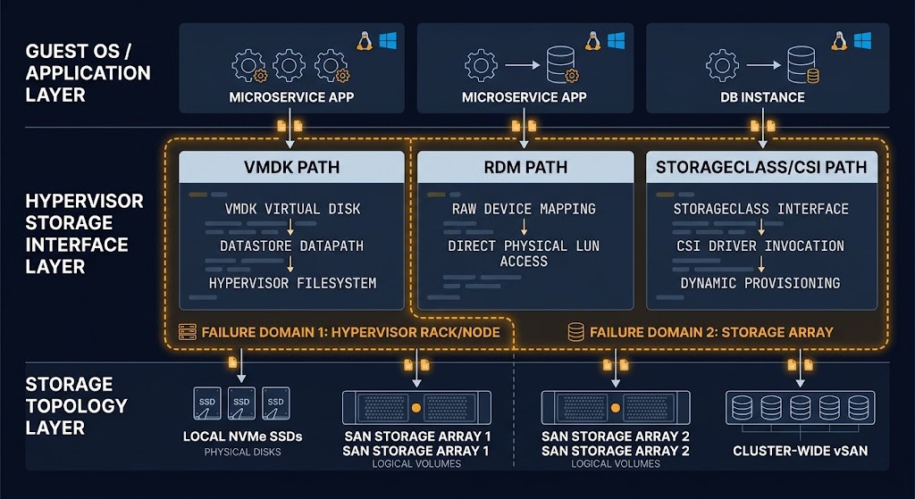
The storage topology decision does not operate in isolation. It operates through a virtualization or container layer that adds its own data path, its own failure surface, and its own management plane complexity. Understanding where the hypervisor storage interface sits — and what it does to the failure domain of the underlying topology — is the difference between a storage architecture that holds under production conditions and one that produces unexplained latency events that never trace cleanly to a root cause.
The hypervisor storage interface introduces three architectural variables that are specific to the virtualization layer. Each one has failure-domain consequences that are distinct from the consequences of the storage topology itself.
Virtual disk format and the failure domain it creates. In VMware environments, the choice between VMDK (virtual disk) and RDM (Raw Device Mapping) is not primarily a performance decision — it is a failure-domain decision. A VMDK places a filesystem abstraction between the guest OS and the underlying storage, which means that storage-level events (LUN failure, snapshot operations, array-level consistency group operations) are mediated by the hypervisor layer before they reach the guest. An RDM bypasses the hypervisor abstraction for block-level access, which means the guest sees storage events directly. For workloads with their own storage-level consistency requirements — Oracle RAC, SQL Server with storage snapshots, any workload relying on array-level consistency groups — the RDM model preserves the storage topology’s failure domain behavior at the guest layer. The VMDK model inserts a new failure surface between the storage topology and the workload.
vSAN as a topology choice, not a feature. When vSAN is enabled in a VMware environment, the storage topology changes from whatever the underlying hardware provides to an HCI topology with a cluster-wide failure domain. This is not a storage upgrade. It is a topology change with all the failure-domain consequences described in the HCI section above. Teams that enable vSAN to reduce storage hardware dependency without modeling the failure domain change are making a topology decision implicitly rather than explicitly.
Kubernetes StorageClass as the storage control plane in code. In Kubernetes environments, the StorageClass is the architectural interface between the application layer and the storage topology. A PVC is not just a capacity request — it is a failure-domain declaration. The StorageClass determines which topology services the PVC, what the reclaim policy is when the PVC is deleted, whether volume expansion is permitted, and what binding mode is used. StorageClass defaults inherited silently from the platform do not match workload SLAs reliably. The most common failure mode is PVCs provisioned against a default StorageClass that serves a different topology than the workload requires — and the mismatch is invisible until the workload’s latency SLA is missed or a volume deletion event triggers an unexpected data retention outcome. For StorageClass architecture and the PVC failure patterns that emerge from it, see PersistentVolumes vs StorageClasses and Kubernetes PVC stuck due to volume node affinity conflicts.
The monitoring gap at the hypervisor storage interface is consistent and consequential. Storage I/O overhead under contention — queue depth accumulation, path failover latency, SCSI reservation conflicts — manifests in application-layer latency metrics before it appears in storage utilization metrics. The application team sees latency. The storage team sees acceptable utilization. The hypervisor layer is where those two observations become consistent with each other, and it is the layer that standard monitoring stacks instrument least completely.
DIAGNOSTIC QUESTION
“Does your StorageClass definition express reclaim policy, binding mode, and volume expansion policy explicitly — or does it inherit platform defaults silently?”
NVMe-oF, RDMA, and the AI Storage Wall
AI and machine learning training workloads broke the assumptions that enterprise storage was designed around. Not incrementally — categorically. The I/O profile of a GPU training job looks nothing like the I/O profile of a transactional database, a VDI session, or a file server. The sequential throughput requirements are an order of magnitude higher. The checkpoint write patterns are bursty in ways that storage systems tuned for steady-state mixed workloads handle poorly. And the latency budget between the GPU and persistent storage is measured in microseconds, not milliseconds — a precision that traditional storage topologies cannot consistently deliver.
The result is the AI storage wall: a performance ceiling that appears when storage architecture designed for conventional workloads is asked to service GPU training jobs at scale. The wall is not a capacity problem. Adding more storage capacity does not help. It is a topology problem — specifically, a data path and failure domain problem.
The local NVMe failure domain boundary. Local NVMe provides the performance profile that GPU training requires: sub-millisecond latency, predictable throughput, no fabric dependency. The failure domain consequence is node-local isolation — which is architecturally correct for training workloads that checkpoint to persistent storage and can restart from the last checkpoint. The problem is scale. A single node’s NVMe capacity limits the dataset size that can be accessed without network traversal. For training runs that require datasets larger than a single node’s local storage, local NVMe alone is insufficient.
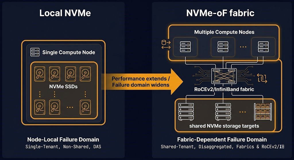
NVMe over Fabrics as the failure domain trade. NVMe over Fabrics (NVMe-oF) extends the local NVMe performance model across a network fabric using RDMA — either RoCEv2 or InfiniBand. The data path goes from local PCIe to a lossless fabric that preserves the low-latency, high-throughput characteristics of NVMe while enabling shared access across multiple compute nodes. The failure domain changes from node-local to fabric-dependent. An NVMe-oF architecture introduces the fabric as a failure surface — fabric congestion, switch failure, or RDMA configuration errors affect storage access for every host on the fabric. That is a wider failure domain than local NVMe, and it must be modeled as such. For fabric architecture decisions between InfiniBand and RoCEv2, see InfiniBand vs RoCEv2 for AI fabric architecture.
The topology class of the fabric underneath NVMe-oF — whether physical fabric, SDN overlay, or a dedicated lossless RDMA network — determines the control plane blast radius and failure behavior of the storage fabric itself. The Modern Networking Logic strategy guide maps these topology classes and their control plane failure modes explicitly, which is the foundation layer any NVMe-oF architecture decision sits on top of.
When NVMe-oF justifies its complexity. The NVMe-oF architecture is justified when three conditions are true: the training dataset exceeds local NVMe capacity, the latency budget for storage access is under two milliseconds, and the team has the network engineering capability to operate a lossless RDMA fabric. When any of those conditions is not true, all-NVMe HCI or all-NVMe Ceph is the correct architecture — lower complexity, acceptable performance, more manageable failure domain. For the specific comparison, see ZFS vs Ceph vs NVMe-oF: The AI Storage Wall and All-NVMe Ceph vs Local ZFS for AI Training.
Erasure coding vs RAID as a failure domain decision. The durability model for AI training storage is not a performance decision — it is a failure-domain decision expressed in data protection policy. RAID provides deterministic rebuild behavior with a fixed performance overhead. Erasure coding provides higher storage efficiency at the cost of more complex rebuild operations and wider failure domain exposure during degraded state. The k+m parameters of an erasure coding configuration define exactly how many simultaneous failures the system can survive. Misconfigured erasure coding — specifically, k+m values selected for storage efficiency without modeling the actual failure domain size — is one of the most consequential silent failure modes in SDS-based AI storage architectures. See RAID vs erasure coding for AI storage SLAs for the decision framework.
Storage Failure Modes
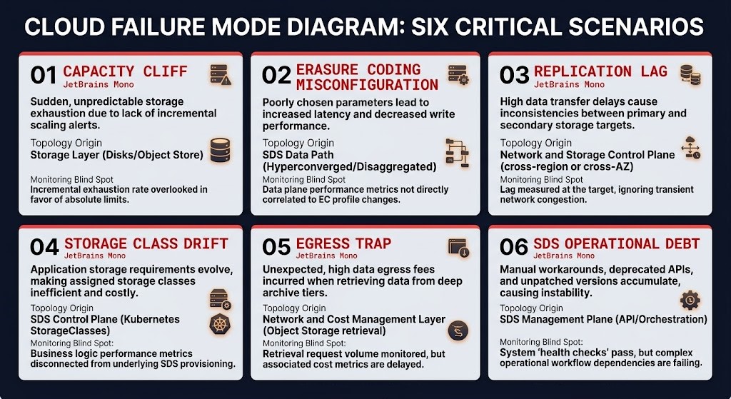
Storage architecture failures are not usually dramatic. They are accumulations of invisible technical debt that manifest as performance degradation, unexpected cost events, and data recovery failures — typically under conditions where the storage system is being asked to do something it was never explicitly designed to handle. The six failure modes below represent the patterns observed most consistently across enterprise storage estates. Each has a distinct trigger, a monitoring blind spot, and a compounding impact.
Storage in IaC — Where the Topology Decision Lives in Code
Storage topology decisions that are not expressed in infrastructure code do not stay decisions. They become undocumented assumptions that drift as the environment evolves, as team members change, and as workloads are deployed by people who did not participate in the original architecture conversation.
The StorageClass is the interface between the infrastructure code layer and the storage topology. It is where the topology decision is either enforced or abandoned. A StorageClass definition that names the topology it serves, specifies the reclaim policy, sets the binding mode, and declares whether volume expansion is permitted is a storage architecture contract expressed in code. A StorageClass inherited silently from platform defaults is an undocumented assumption waiting to become a latency SLA miss or an unexpected data retention outcome.
Three rules apply to storage decisions in IaC, following the same discipline as compute:
First: StorageClass selection and PVC configuration belong in the initial Terraform or Helm commit, not as a post-provisioning correction. Reclaim policy is a data lifecycle decision. Binding mode is a scheduling and availability decision. Volume expansion policy is a capacity management decision. All three belong at provisioning time. Retrofitting them after workloads are running requires a migration or a storage class migration procedure — both carry risk and are typically deferred indefinitely in production environments.
Second: storage topology should be a named variable with validation, not a hardcoded default. An explicit var.storage_topology with defined allowed values and input validation makes the topology choice visible in code reviews and enforceable through CI/CD. It prevents the pattern where a module’s default StorageClass serves a topology that no subsequent deployer ever questioned because it was never surfaced as a decision point.
Third: capacity commitments and storage tier decisions made outside the IaC layer must be surfaced as inputs to the provisioning model. The disconnect between cloud block storage reserved capacity purchased in the billing console and Kubernetes PVCs provisioned in Terraform creates invisible mismatch between committed capacity and actual utilization. The IaC layer should have visibility into active storage commitments as a guard against both over-provisioning and commitment waste.
The storage topology decision made at provisioning time is the failure domain, the latency profile, and the operational model commitment for the life of the workload. For IaC patterns that enforce infrastructure decisions at the code layer, see Deterministic IaC and Terraform policy as code and Control Plane Shift: Infrastructure Decisions 2026. For Kubernetes storage architecture specifically, the PersistentVolumes vs StorageClasses post covers the StorageClass as control plane in detail.
Decision Framework — When Each Topology Is the Right Call
Deterministic sub-millisecond latency is a hard architectural requirement. Failure domain isolation to a single node is a design constraint. Workload accepts compute-storage co-location model. GPU training checkpoint I/O or high-frequency database access patterns.
Mixed workload environment where converged operational simplicity outweighs per-workload performance isolation. Compute and storage scale at similar rates. Cluster-wide failure domain is acceptable after explicit modeling.
Platform engineering capacity to own the management plane exists and is staffed. Kubernetes-native PVC portability is an architectural requirement. Scale-out storage independent of compute is required. Operator-controlled failure domain granularity is a design requirement.
Existing investment with a justified compliance or performance case. Vendor-certified hardware configuration is a regulatory requirement. Legacy application portfolio where migration risk outweighs topology modernization benefit.
Backup and archival targets. Cold-path analytics. Stateless application data where latency floor is acceptable. Any workload where operational simplicity outweighs latency predictability and egress cost modeling has been done explicitly.
Compute and storage scale requirements diverge materially. Per-workload storage performance isolation is a hard requirement. The cluster-wide failure domain has not been explicitly modeled and accepted.
Platform engineering capacity to own the management plane doesn’t exist. The topology decision was driven by licensing cost comparison rather than operational model matching. The cluster will be managed reactively rather than proactively.
There is no existing investment to protect and no compliance requirement that specifically mandates vendor-certified hardware. The cost premium is not justified by a documented performance or regulatory requirement.
Recovery SLA requires low-latency rehydration. Egress cost for large-scale reads was not modeled at storage design time. Sovereign or air-gap requirements prohibit provider API dependency.
Decision table — workload profile to recommended topology:
| Workload Profile | Recommended Topology | Key Signal | Avoid When |
|---|---|---|---|
| GPU AI training, checkpoint I/O | Local NVMe or NVMe-oF | Sub-ms latency, failure isolation required | HCI shared pool — saturates under sequential writes |
| General enterprise VMs, VDI | HCI | Converged ops, stable mixed-workload profile | Compute and storage scale requirements diverge |
| Kubernetes-native microservices | SDS (Ceph / Rook / Longhorn) | PVC portability, scale-out required | Platform engineering capacity to own management plane doesn’t exist |
| Legacy application portfolio, regulated | SAN/NAS (existing) | Certified compliance path, existing investment | Greenfield — no reason to inherit the lock-in |
| Backup, archival, cold analytics | Cloud-native object | Elastic retention, no upfront capacity | Recovery SLA requires low-latency rehydration |
| Sovereign / air-gap compute | Local NVMe + SDS hybrid | Control plane isolation, no provider API dependency | Cloud-native — egress and API dependency conflicts with isolation requirement |
| AI training at fabric scale | NVMe-oF (RoCEv2 / InfiniBand) | Dataset exceeds local capacity, latency < 2ms | Team lacks lossless fabric operational capability |
What Breaks First
Storage architecture failures follow a consistent sequence. The signals appear in a specific order — and the early signals are almost always in the wrong monitoring layer to catch them before damage is done.
- Latency spikes before utilization alerts fire. Queue depth accumulates at the storage controller or fabric layer before IOPS or throughput metrics saturate. Application teams see latency. Storage dashboards show acceptable utilization. The gap between those two observations persists until someone queries queue depth directly.
- Rebuild windows extend before capacity alarms trigger. A degraded OSD or failed RAID member begins a rebuild operation that competes with production I/O. The rebuild completes slowly — or doesn’t complete — because production workloads are consuming the I/O bandwidth the rebuild needs. Capacity metrics stay green. The cluster’s durability posture is degrading the entire time.
- PVC drift appears in application behavior before Kubernetes tickets are opened. A workload provisioned from an incorrect StorageClass is serving requests against the wrong topology. The application latency is elevated. No alerts fire because the PVC is bound, the pod is running, and storage utilization is nominal. The root cause traces to a StorageClass mismatch that has been in production since the initial deployment.
- Queue depth rises before throughput metrics fall. Under I/O pressure, queue depth is the leading indicator. Throughput degrades when the queue is saturated — but queue depth accumulation begins much earlier. Monitoring stacks that alert on throughput without monitoring queue depth miss the failure mode at its most actionable point.
- Recovery path fails validation before primary storage shows any degradation signal. The most dangerous storage failure mode is a recovery path that has never been tested under production load conditions. A backup that restores successfully in a test window may fail or exceed its RTO under the I/O load of a real recovery event. The recovery path fails before the primary storage shows any sign of stress.
Storage topology doesn’t operate in isolation. The data path connects directly to compute placement constraints, network fabric decisions, and IaC enforcement patterns. The pages below cover each adjacent layer.
YOU’VE READ THE ARCHITECTURE.
NOW TEST WHETHER YOUR ENVIRONMENT HOLDS.
Your storage topology decisions may have been made without explicitly modeling the failure domain, the operational model, or the exit path. A Storage Topology Assessment maps your current architecture against the Topology Model and surfaces the gaps before a failure event or migration forces them into view.
Storage Topology Assessment
A vendor-neutral review of your storage architecture against the Rack2Cloud Storage Topology Model — topology by topology, failure domain by failure domain, before a migration or failure event forces the conversation.
- > SDS / HCI fit analysis
- > Topology risk mapping
- > Ceph / SAN / NVMe-oF decision support
- > Exit path and failure domain review
Architecture Playbooks. Every Week.
Field-tested storage and infrastructure blueprints delivered weekly — topology decisions, SDS operational patterns, NVMe-oF architecture, and the failure modes that compound quietly until they don’t.
- > Storage topology decision frameworks
- > SDS operational model field notes
- > AI storage architecture patterns
- > IaC storage enforcement patterns
Zero spam. Unsubscribe anytime.
Architect’s Verdict
Enterprise storage architecture is failure-domain design. That framing is not an abstraction — it is the most precise description of what the storage topology decision actually commits you to. The topology you choose at provisioning time sets where failure localizes, what survives loss, what rebuilds under pressure, and what degrades first. Those consequences are architectural, not operational. You cannot patch them with a firmware update, a monitoring tool, or a capacity addition after the commitment has hardened.
The SDS operational truth has been stated on this page more than once because it is the truth that the largest category of storage architecture mistakes depends on not being stated clearly. Organizations running Ceph clusters in permanently degraded states, with rebalancing operations that have been pending for weeks and CRUSH maps that have drifted from their original configuration, did not choose the wrong software. They chose a topology whose operational burden they were not resourced to own. SDS moved the management plane overhead from the vendor’s support team to the operator’s platform engineering team. That is not a reduction in operational cost. It is a transfer of operational responsibility — and the transfer only goes well when the receiving team was sized and equipped to handle it before the cluster was deployed.
The AI storage wall is not a future concern. It is a present constraint for any organization running GPU training workloads at scale against storage infrastructure designed for conventional enterprise I/O profiles. The checkpoint I/O patterns of training jobs, the sequential throughput requirements of large dataset ingestion, and the microsecond latency budgets of GPU-to-storage data paths are categorically different from the mixed random I/O that HCI clusters, SAN arrays, and cloud block storage are designed to service. NVMe-oF changes the failure domain in exchange for extending the performance model. That tradeoff must be modeled explicitly — performance gains purchased at the cost of a wider failure domain are not universally positive.
The IaC dimension is not optional. Storage topology decisions that are not expressed in infrastructure code as explicit StorageClass definitions, named topology variables, and validated reclaim policies do not stay decisions. They become invisible assumptions that propagate through every workload provisioned from the same template, survive team turnover, and surface as unexplained failure events long after the architectural context for them has been lost.
The topology you choose is the latency budget, the failure domain, and the exit path. Model all three before you sign the PO.
Frequently Asked Questions
Q1: What is the difference between SDS and HCI in enterprise storage architecture?
A: The difference is where the management plane lives and how the failure domain is bounded. HCI converges compute and storage into a single platform where the vendor’s management layer handles data distribution, replication, and recovery across the cluster — the failure domain is cluster-wide and the management overhead is low. SDS decouples storage management from hardware entirely, placing the management plane under full operator control — the failure domain is operator-defined and the management overhead scales with the operator’s platform engineering capacity. HCI optimizes for operational simplicity at the cost of per-workload performance isolation. SDS optimizes for flexibility and portability at the cost of operational complexity. Neither is inherently better. Both require that the operational model assumption be explicitly matched to the team’s capacity before the topology is selected.
Q2: When does NVMe-oF justify its operational complexity over all-NVMe HCI?
A: Three conditions must all be true. The training dataset or working set exceeds what local NVMe capacity can serve without network traversal. The storage access latency budget is under two milliseconds — a threshold that positions HCI’s shared-pool latency as inadequate. And the team has the network engineering capability to operate a lossless RDMA fabric at production scale. When any one of those conditions is not met, all-NVMe HCI or all-NVMe Ceph provides acceptable performance at substantially lower operational complexity. NVMe-oF’s failure domain trade — extending from node-local to fabric-dependent — is justified only when the performance requirement genuinely cannot be met within the local or HCI topology.
Q3: How should StorageClass decisions be expressed in Terraform and Kubernetes manifests?
A: StorageClass selection should be an explicit named variable in every workload provisioning template, not a default inherited from the platform. Three parameters must always be explicitly declared: reclaim policy (Retain vs Delete — a data lifecycle decision with permanent consequences), binding mode (Immediate vs WaitForFirstConsumer — a scheduling and availability decision), and whether volume expansion is permitted. These parameters should be validated through input constraints in Terraform modules and through admission controllers in Kubernetes. Any PVC provisioned without explicit StorageClass selection is an undocumented assumption about failure domain and data lifecycle that will eventually produce an unexpected outcome.
Q4: When does cloud-native block or object storage become an egress cost trap?
A: At three specific events: backup rehydration during a recovery operation, cross-region analytics reads against large datasets, and data repatriation during a cloud exit or storage migration. All three are retrieval events where the cost and latency of reading data at cloud rates was not modeled at write time. The trap is structural — cloud storage cost models are optimized to make write decisions easy and retrieval consequences opaque. The correction is to model retrieval scenarios explicitly at storage design time: simulate a full restore from the cloud target, measure both elapsed time and egress cost, and validate both against the stated RTO and budget before the topology is committed.
Q5: What makes Ceph the right choice — and when is it the wrong one?
A: Ceph is the right choice when scale-out storage independent of compute is a genuine architectural requirement, when Kubernetes PVC portability across nodes matters, and — most importantly — when the team operating it has the platform engineering capacity to own the management plane proactively. Ceph is the wrong choice when the topology decision was driven primarily by licensing cost comparison with hardware SAN. It is the wrong choice when the cluster will be managed reactively — responding to degraded states rather than preventing them. And it is the wrong choice when the team does not have the operational knowledge to configure CRUSH maps correctly, validate erasure coding parameters against actual failure domain size, and maintain cluster health through upgrade events. The software is not the variable. The operational model is.
Q6: How does storage topology interact with Kubernetes PVC scheduling and failure domains?
A: The StorageClass determines which storage topology services a PVC, which means it determines the failure domain that the PVC’s data inhabits. A PVC serviced by a local NVMe provisioner inherits a node-local failure domain — pod scheduling must place the pod on the node that owns the PVC, which constrains Kubernetes scheduler decisions and introduces a node-affinity dependency. A PVC serviced by an SDS provisioner inherits the failure domain configured in the SDS cluster’s placement policy. A PVC serviced by cloud-native block storage inherits a provider-managed, opaque failure domain. The interaction between StorageClass selection, PVC binding mode, and scheduler node affinity must be modeled together — treating them as independent decisions produces pods that cannot be scheduled on available nodes, PVCs that bind to the wrong topology, or workloads that violate their own failure domain requirements without any explicit error.
Q7: When does an enterprise storage architecture justify a full reassessment?
A: Four triggers: a pricing or contract event that materially changes the TCO of the current topology — Broadcom’s VMware acquisition is the most recent example that forced SAN/vSAN economics into question across a large installed base. A migration or replatforming initiative that forces a full workload inventory and makes topology mismatches visible. A performance investigation that traces latency or throughput degradation to storage topology rather than application behavior or compute capacity. And a compliance review or incident that surfaces failure domain assumptions that were never explicitly modeled or verified. The Migration Readiness Assessment is structured to address the first three. If you are in the middle of a VMware exit, an SDS evaluation, or a cloud storage cost optimization initiative, the assessment maps your current topology against the Storage Topology Model before the migration commitment hardens.