

COMPUTE EXECUTION ARCHITECTURE
Making provisioned compute behave like executed compute — scheduling, density ceilings, and contention under load.
SPECIALIZATION TRACK — COMPUTE EXECUTION ARCHITECTURE
- Track Discipline: The mechanics by which provisioned compute becomes executed compute — vCPU:pCPU mapping, scheduling, overcommit, runtime overhead, and density ceilings.
- Primary Architectural Tension: Allocation determinism vs density economics — the more workloads packed per host, the wider the gap between provisioned and executed compute.
- Architectural Boundary: Does not govern the storage IO path or network fabric — those are covered in the Storage Architecture and Networking Architecture Tracks. Does not govern capacity modeling, latency budgets, or forecasting — that is the Performance Modeling Track. This Track governs the compute execution mechanics those disciplines consume.
- Domain Path Relationship: Deepens Stages 2–4 of the Virtualization Architecture Path — Control Plane Architecture, Storage and Network Integration, and Deterministic Operations — which treat scheduling and execution at breadth without opening the mechanics.
- Who This Track Is For: Your cluster averages read healthy but specific workloads stutter under load. You suspect scheduling contention or density pressure, but the dashboards give you no signal to confirm it.
Compute architecture is the discipline that governs how provisioned resources become executed resources — and understanding it begins with a constraint that most environments never model explicitly. Allocation is not execution. Every hypervisor, scheduler, runtime, and kernel arbitration layer transforms what was allocated into something the workload actually receives, and the gap between those two numbers is where most virtualization performance problems live. This Track covers that gap in full: vCPU scheduling, NUMA locality, runtime overhead, density ceilings, and the failure modes that emerge when execution diverges from allocation without warning.
Specialization Tracks deepen specific architectural disciplines across multiple maturity stages without replacing the progression logic of the Domain Path itself. The Virtualization Architecture Path covers compute at the breadth required to move through the maturity stages — it establishes that workloads are scheduled, that control planes govern placement, and that deterministic operations require disciplined capacity management. What it does not open is the execution-physics layer beneath those decisions: the mechanics by which a vCPU becomes CPU time, a memory allocation becomes a NUMA access, and a provisioned density becomes a contention ceiling. The operational condition that makes Track depth necessary is specific: when cluster averages look healthy but workloads don’t behave as designed, breadth-level understanding is insufficient.
>_ WHY THIS TRACK EXISTS
Compute is provisioned as a static allocation but executed as a contended, scheduled, kernel-enforced resource — those are different numbers. Organizations that size to the allocation produce clusters that read healthy on average while individual workloads absorb CPU ready-time, NUMA penalties, and memory reclaim that no dashboard surfaces. The Virtualization Architecture Path treats the scheduler as a black box: it covers control-plane mechanics without opening vCPU:pCPU mapping, overcommit ceilings, or the runtime overhead that compresses available capacity below what provisioning records show. This Track provides the execution-physics depth to predict workload behavior before deployment and to model the density ceiling before it becomes a failure domain.
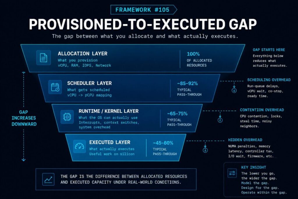
Framework #105 — The Provisioned-to-Executed Gap
The difference between the compute resources an administrator allocates and the compute resources a workload actually receives, once scheduling, contention, NUMA locality, overcommit, and runtime overhead are applied. The Provisioned-to-Executed Gap unifies vCPU:pCPU mapping, CPU ready-time, NUMA locality, scheduler placement decisions, runtime and controller overhead, density ceilings, and Kubernetes requests-vs-limits behavior under one architectural model — all are manifestations of the same underlying phenomenon.
Allocation is not execution. The Provisioned-to-Executed Gap is the architecture of that difference.
WHAT THIS TRACK IS NOT
01 — NOT A CPU VENDOR OR HARDWARE SPECIFICATION REFERENCE
This Track covers how hypervisors, schedulers, and kernels deliver — or fail to deliver — provisioned compute to workloads, not which processor generation to purchase.
02 — NOT A STEP-BY-STEP SIZING OR CAPACITY PLANNING GUIDE
This Track covers the tradeoffs, failure modes, and architectural consequences of overcommit and density decisions — the mechanics that any sizing methodology must account for.
03 — NOT PERFORMANCE MODELING
Compute Architecture owns the execution mechanics — scheduling, overhead, and density. Performance Modeling consumes those mechanics to produce capacity headroom numbers and latency budgets. The two disciplines are sequentially dependent, not interchangeable.
04 — NOT STORAGE OR NETWORK ARCHITECTURE
This Track is scoped to the compute execution path. Storage IO latency, network fabric throughput, and distributed system mechanics are covered in their respective Specialization Tracks.
COMPUTE ARCHITECTURE — READING SCOPE
| Scope | Coverage | Estimated Time |
|---|---|---|
| Core Reading Sequence | Clusters 01–02 — execution physics and scheduling authority | ~1.5–2 hr |
| Full Track | All 4 clusters — foundations through density ceilings and compute failure domains | ~3–4 hr |
>_ WHERE TO ENTER THIS TRACK
Start at Cluster 01 if the mechanics of the Provisioned-to-Executed Gap are not already part of how you reason about workload placement and capacity decisions. The cluster establishes the execution-physics foundation the rest of the Track builds on — overcommit modeling, density ceilings, and failure-domain analysis all depend on understanding what happens between allocation and execution.
You can enter at Cluster 03 if the following three conditions apply to how you currently operate:
- You already model CPU ready-time, NUMA locality, and vCPU:pCPU ratios as design constraints rather than post-incident diagnostics
- You have encountered a node-density ceiling where scheduler or memory pressure blocked workload placement despite available provisioned capacity
- You have modeled overcommit risk explicitly and understand where that ceiling transitions from an efficiency lever into a failure domain
If all three apply, Cluster 03 covers the density and overhead mechanics that move beyond execution-physics foundations. If any require translation, begin at Cluster 01.
>_ READING SEQUENCE
Each cluster below is organized by architectural problem. Every cluster answers: what becomes architecturally unstable if this discipline is misunderstood?
What the Hypervisor, Scheduler, and Kernel Actually Deliver
Compute architecture begins with a simple architectural reality: provisioned compute and executed compute are not the same resource. Hypervisors, schedulers, runtimes, NUMA boundaries, and kernel arbitration layers transform allocated capacity into delivered capacity. Understanding that translation is the foundation for every density, contention, and performance decision that follows. This cluster anchors Framework #105 — the Provisioned-to-Executed Gap — and establishes why cluster-average metrics are structurally insufficient for workload-level analysis.
Who Gets CPU When Demand Exceeds Supply
Scheduling determines which workloads receive compute resources first, which workloads wait, and which workloads degrade. Density failures often begin as scheduling decisions long before they appear as capacity shortages. This cluster covers scheduling authority — the layer that arbitrates compute access under contention — and the placement decisions that determine which workloads encounter contention in the first place. The hypervisor scheduler is the original instance of scheduling intelligence attracting operational authority; understanding its mechanics applies directly to Kubernetes cluster schedulers, GPU placement engines, and the AI fabric layer that inherits the same pattern.
The Real Per-Host Capacity Ceiling
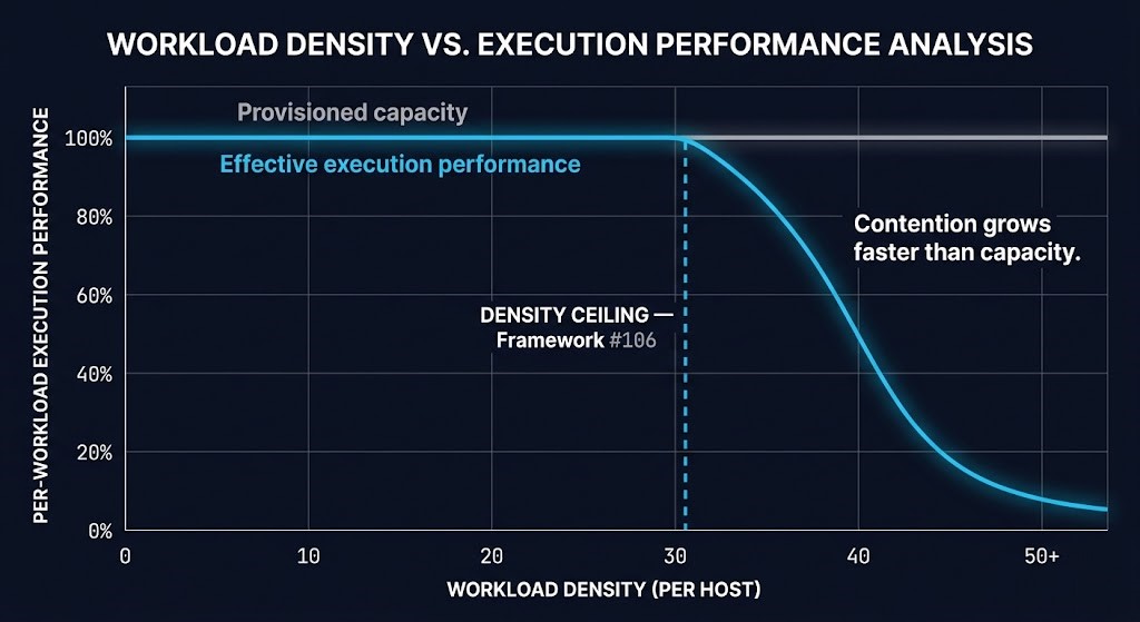
Most virtualization environments reach their density ceiling long before they exhaust raw hardware resources. Runtime overhead, controller tax, memory pressure, maintenance headroom, and scheduler contention compress the usable capacity available to workloads below what provisioning records show. The distance between provisioned capacity and effective capacity is not a configuration error — it is the structural cost of the virtualization and container layers that sit between allocation and execution. This cluster introduces Framework #106 — the Density Ceiling — and covers the three primary sources of overhead that define it.
Framework #106 — The Density Ceiling
The point at which additional workload placement increases contention faster than usable compute capacity. Below the Density Ceiling, density is an efficiency lever. Above it, the cluster appears healthy on aggregate metrics while latency and stall time rise for individual workloads. The Density Ceiling applies across hypervisor, container, and accelerator environments — and reappears in GPU cluster scheduling, Kubernetes bin-packing, AI inference placement, and HCI capacity planning as the same structural phenomenon.
When Density Failures Become Cluster Events
At density, compute failure domains cascade. Node loss does not simply remove capacity — it creates placement pressure on remaining hosts, triggers eviction chains, and can simultaneously expose quorum risk in clustered configurations. The failure domain of a compute-dense environment is not a node; it is the cascade pattern that begins the moment any node loses headroom below the Density Ceiling. This cluster covers the failure mechanics that density decisions create before the first incident ticket opens.
PROVISIONED VS EXECUTED COMPUTE
| Layer | What Administrators See | What Workloads Experience |
|---|---|---|
| Allocation | vCPU assigned, memory reserved | Potential CPU access — no execution guarantee yet |
| Scheduler | Resource listed as available | Wait time introduced — CPU ready, placement delay, queue position |
| Runtime | Capacity appears free in aggregate metrics | Overhead consumes resources — controller tax, runtime daemons, kernel arbitration |
| Failure Event | Reported capacity unchanged | Effective compute shrinks — N-1 triggers reclaim, eviction pressure, and placement contention |
| Density Ceiling (Framework #106) | Cluster reads healthy on aggregate | Latency and contention rise — individual workloads stall while dashboards show available capacity |
>_ TRACK FAILURE PATTERNS
Five failure patterns that emerge when compute architecture is handled at Domain Path breadth without Track-level depth.
| Failure Pattern | Architectural Consequence |
|---|---|
| Sizing to allocation, not execution | Cluster averages read healthy while individual workloads absorb CPU ready-time, NUMA penalties, and memory reclaim that no cluster-level dashboard surfaces. |
| Treating overcommit as free capacity | Framework #106 Density Ceiling is crossed silently — latency variance rises and workloads stall before any capacity signal fires. |
| Ignoring controller and runtime overhead | Effective density is far below provisioned figures; phantom headroom is consumed before the first workload deploys, producing contention at densities that look safe on paper. |
| No N+1 compute headroom reserved for maintenance | Rolling upgrades evict workloads into contention at exactly the moment density is highest — a maintenance window becomes an outage window. |
| Density without failure-domain containment | A single node loss triggers placement pressure across remaining hosts, eviction chains, and quorum risk simultaneously — the failure domain is the cluster, not the node. |
>_ CROSS-TRACK DEPENDENCIES
Tracks share foundational mechanics across disciplines. Understanding which Tracks compound with this one prevents siloed architectural analysis.
| Depends On | Dependency Direction | Why It Matters |
|---|---|---|
| Storage Architecture | Bidirectional | HCI architectures couple compute and storage on the same node; controller overhead is a shared deduction from both — the density ceilings in each Track are not independent. |
| Networking Architecture | Upstream Constraint | Node-to-node latency from the fabric bounds distributed compute execution physics — network topology sets an upstream constraint that no compute scheduling decision can override. |
| Performance Modeling | Downstream Consumer | Performance Modeling consumes Framework #105 and Framework #106 as inputs to produce capacity headroom numbers and latency budgets — it models the gap this Track defines. |
| HCI Failure-State Architecture | Bidirectional | Framework #88 Failure-State Envelope and Framework #106 Density Ceiling are shared failure architecture — HCI density and compute failure domains cannot be analyzed independently. |
| Virtualization Architecture Path | Domain Path Parent | Establishes the maturity progression — control plane, scheduling, and deterministic operations — that this Track deepens at the execution-physics layer for Stages 2–4. |
>_ TRACK GRADUATES CAN NOW
Completing this Track changes one thing: you no longer size compute to allocation. You size to executed capacity — with scheduling, overhead, and failure domains already accounted for in the model. That precision propagates directly into the Performance Modeling Track, where Frameworks #105 and #106 become the inputs for capacity headroom and latency budget work. Allocation is not execution — graduates of this Track build architectures that account for that difference before workloads deploy, not after they stall.
- Predict workload execution behavior before deployment — accounting for NUMA locality, vCPU:pCPU scheduling, and CPU ready-time as design constraints rather than post-incident diagnostics.
- Model the real density ceiling per host, including controller overhead, runtime daemons, and N+1 maintenance headroom — not provisioned capacity minus a margin of intuition.
- Diagnose “healthy average, stalled workload” conditions by instrumenting execution-layer signals rather than relying on cluster-average metrics that structurally cannot surface individual workload contention.
- Size compute environments for rolling maintenance without workload impact by explicitly modeling headroom against the Density Ceiling, not raw provisioned allocation figures.
- Apply Frameworks #105 and #106 to Performance Modeling capacity and latency-budget work — these mechanics are what the Performance Modeling Track consumes to produce actionable headroom numbers.
>_ WHERE DO YOU GO FROM HERE
YOUR DENSITY MODEL MAY NOT MATCH YOUR EXECUTION MODEL
Provisioned capacity, scheduler behavior, controller overhead, and maintenance headroom rarely align the way dashboards imply. The Infrastructure Architecture Review identifies the execution-physics assumptions creating hidden contention, false headroom, and density ceilings before they surface as operational instability.
Infrastructure Architecture Review
- > Compute execution analysis
- > Density ceiling validation
- > Overcommit risk assessment
- > Failure-domain review
Architecture Playbooks. Field-Tested Blueprints.
Field-tested blueprints for compute architecture — execution-physics decisions that determine whether density is an efficiency lever or a failure domain.
- > Scheduling determinism
- > Density modeling
- > Compute failure domains
- > Capacity governance
Zero spam. Unsubscribe anytime.
>_ FREQUENTLY ASKED QUESTIONS
Q: What is compute architecture in the context of enterprise virtualization?
A: Compute architecture is the discipline that governs how provisioned compute resources — vCPU allocations, memory reservations, and node capacity — become the execution resources workloads actually receive. It covers the mechanics of the hypervisor scheduler, NUMA locality, overcommit modeling, runtime overhead, and density ceilings: the full translation path from allocation to execution.
Q: What is the Provisioned-to-Executed Gap and why does it matter?
A: The Provisioned-to-Executed Gap is the difference between the compute resources an administrator allocates and the compute resources a workload actually receives, once scheduling, contention, NUMA locality, overcommit, and runtime overhead are applied. It matters because environments sized to allocation rather than execution produce clusters that read healthy on average while individual workloads absorb CPU ready-time, NUMA penalties, and memory reclaim that aggregate dashboards never surface.
Q: How is Compute Architecture different from Performance Modeling?
A: Compute Architecture covers the mechanics — vCPU:pCPU mapping, scheduling authority, runtime overhead, and density ceilings. Performance Modeling consumes those mechanics to produce capacity headroom numbers, latency budgets, and contention forecasts. The two disciplines are sequentially dependent: you need the mechanics before you can model the outcomes. This Track covers the mechanics; the Performance Modeling Track applies them.
Q: Who should take this Track vs completing the Virtualization Architecture Domain Path stages?
A: The Domain Path stages cover scheduling and compute at the breadth required to move through the maturity model — they establish that compute is virtualized, scheduled, and governed. This Track is for architects who need to open the execution-physics layer beneath those decisions: when cluster averages look healthy but workloads don’t behave as designed, when density decisions are made on provisioned numbers rather than executed capacity, or when contention is diagnosed after the fact rather than modeled before deployment.
Q: Why do clusters read healthy on average while individual workloads stall?
A: Cluster-average metrics aggregate CPU utilization, memory usage, and throughput across all hosts and workloads. Individual workloads experience CPU ready-time (wait for scheduler access), NUMA penalty (non-local memory access latency), and runtime overhead (controller tax, daemon consumption) that only appear at the per-workload execution layer. A cluster at 35% average CPU utilization can simultaneously have workloads absorbing significant ready-time — the average obscures the distribution.
Q: How does overcommit become a failure domain rather than an efficiency lever?
A: Overcommit is an efficiency lever below the Density Ceiling — the point at which additional workload placement increases contention faster than usable compute capacity. Below that threshold, overcommit compresses idle cycles into useful work. Above it, each additional workload increases ready-time and latency variance for all workloads on the host. The failure domain is not a configuration; it is a threshold crossed silently when density decisions are made against provisioned numbers rather than executed capacity.
>_ RELATED SYSTEMS
Hypervisor mechanics and core virtualization foundations — the architectural vocabulary this Track builds on at the execution-physics layer.
Open Stage →Deterministic operations across the platform lifecycle — where the density and scheduling mechanics from this Track become operational design constraints at Stage 4 maturity.
Open Stage →The Modern Infrastructure pillar page for compute logic — hardware topology, NUMA design, and the architectural decisions that precede virtualization deployment.
Open Pillar →GPU scheduling extends the density ceiling and scheduling-authority mechanics from this Track into accelerator placement — the highest-density compute environment class.
Open Pillar →The Completely Fair Scheduler documentation — the kernel-level enforcement layer that all Linux-based hypervisors and container runtimes build on.
Open Reference →CPU ready-time, memory ballooning, and resource pool mechanics — the scheduler behavior reference for vSphere-based execution-physics analysis.
Open Reference →