ACCELERATED COMPUTE ARCHITECTURE
GPU execution physics, VRAM constraints, accelerator economics, and interconnect topology — the mechanical vocabulary every AI infrastructure decision depends on.
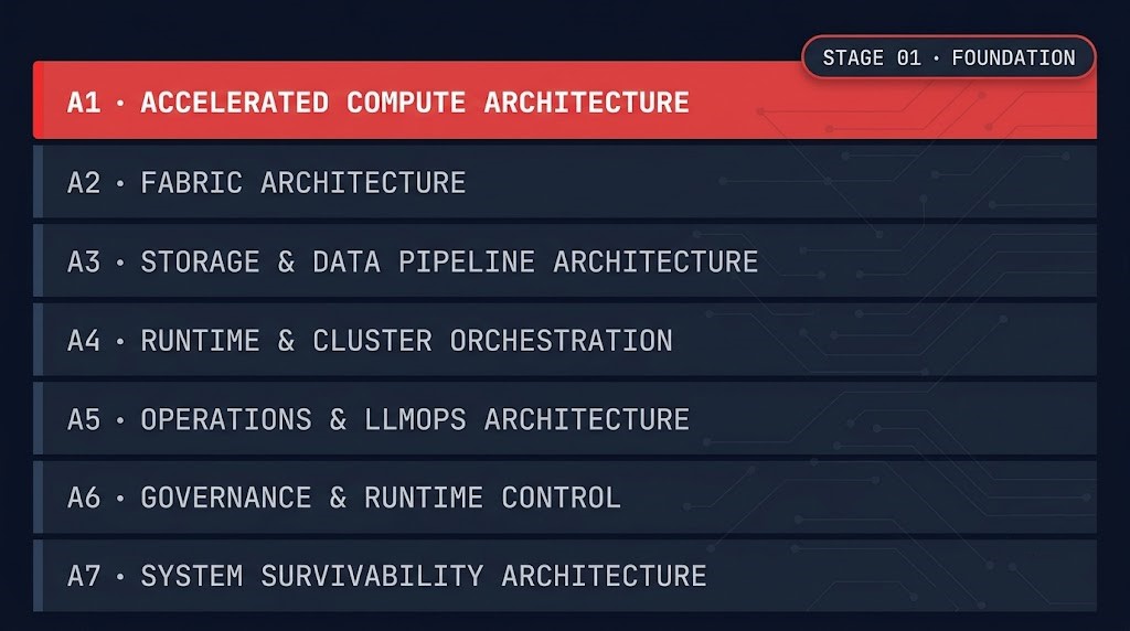
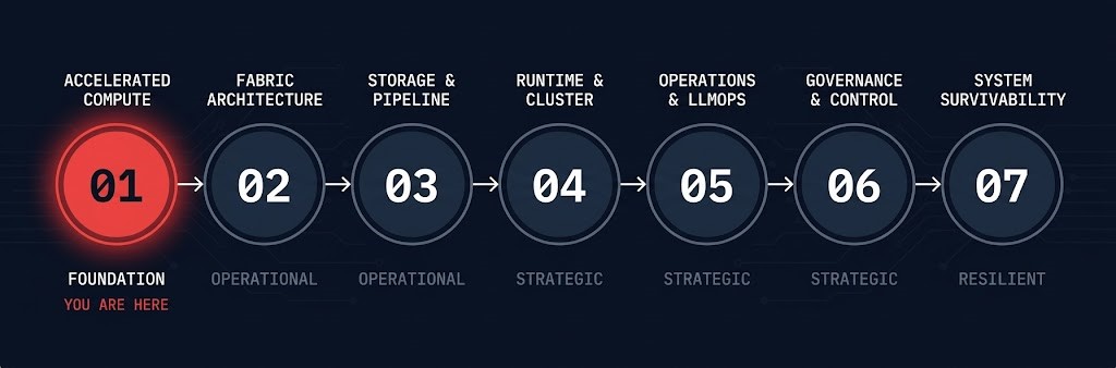
MATURITY POSITION — AI INFRASTRUCTURE STAGE 01 OF 07
- Current Stage: Foundation — Maturity Stage 01 of 07
- Primary Architectural Concern: Why accelerated compute behaves differently from general-purpose infrastructure — execution locality, memory bandwidth ceilings, and interconnect topology as first-order architectural constraints, not background infrastructure details
- Primary Failure Mode: Treating GPUs as fast CPUs — producing VRAM fragmentation, interconnect bottlenecks, and capacity models that cannot explain why expensive hardware idles while workloads queue
- Stage Outcome: Ability to evaluate accelerator selection, VRAM constraints, interconnect topology tradeoffs, and the economics of provisioned vs. executed capacity before committing to hardware or orchestration policy
- Next Stage: Fabric Architecture →
Accelerated compute architecture is the Foundation stage of the AI Infrastructure Architecture Path — the layer where the physics of GPU execution, VRAM constraints, and interconnect topology become architectural constraints rather than hardware specifications. Every decision made at higher layers — how workloads are scheduled, where data pipelines are staged, how the control plane enforces placement policy — inherits its assumptions from what is understood here. When those assumptions are wrong, failures appear at the orchestration layer, the operations layer, and the survivability layer, but the root cause lives at the substrate.
The central concept introduced at this stage is Framework #114 — the Accelerator Locality Boundary: the architectural limit beyond which memory movement becomes more expensive than computation, causing execution performance to be governed by data placement and interconnect topology rather than accelerator capability. This framework is not abstract. It predicts specific failure modes — VRAM fragmentation under multi-tenant inference, gang scheduling failures under insufficient NVLink topology, and capacity models that diverge from executed throughput at scale. Engineers who internalize this boundary before touching the scheduler, the fabric, or the operations stack diagnose failures faster and design infrastructure that holds under production load.
FRAMEWORK #114 — ACCELERATOR LOCALITY BOUNDARY
The Accelerator Locality Boundary is the architectural limit beyond which memory movement becomes more expensive than computation, causing execution performance to be governed by data placement and interconnect topology rather than accelerator capability. It unifies VRAM constraints, PCIe vs. NVLink topology, memory bandwidth ceilings, and GPU-to-GPU communication into a single diagnostic boundary.
AI infrastructure failures rarely originate at the layer where their symptoms appear. A scheduler that looks inefficient is often sitting on a VRAM fragmentation problem. A fabric that looks undersized is often compensating for a locality constraint that should have been resolved at compute selection. A capacity plan that looks correct on paper diverges from executed throughput because allocated GPUs and executable GPUs are not the same thing.
The Accelerator Locality Boundary is the diagnostic concept that separates accelerator-physics failures from orchestration, networking, and operations failures. Without it, the wrong layer gets re-engineered — and the substrate problem recurs under the next workload that exceeds the same constraint.
>_ What This Stage Is Not
01 — NOT A GPU PROCUREMENT GUIDE
Accelerator selection is an output of understanding execution physics — not a purchasing exercise. This stage builds the constraint vocabulary that makes hardware decisions legible, not a comparison matrix of GPU SKUs.
02 — NOT A CUDA OR KERNEL OPTIMIZATION TUTORIAL
The concern here is architectural consequence, not programming model. How GPU kernels execute internally is a software engineering problem. How GPU execution constraints propagate into infrastructure design is an architecture problem — and this is the latter.
03 — NOT AN INTRODUCTION TO AI GENERALLY
This stage assumes you know why AI infrastructure is being built. It covers how the hardware constrains what gets built on top of it — the execution physics that determine whether a proposed workload is viable at the scale and topology being planned.
04 — NOT AN ORCHESTRATION STAGE
Scheduling, placement, admission control, quota enforcement, and cluster governance belong to A4 — Runtime & Cluster Orchestration. This stage builds the substrate knowledge that makes those decisions legible. The scheduler cannot correct a VRAM constraint it does not know exists.
| Stage | Estimated Depth | Last Reviewed |
|---|---|---|
| A1 — Accelerated Compute Architecture | ~4–5 hrs | June 2026 |
>_ Where to Enter This Stage
Foundation stage — default entry is the first article in the reading sequence. No prior AI infrastructure knowledge is assumed beyond an understanding of why accelerated compute is being deployed.
Skip-ahead criteria: If you can articulate why NVLink topology affects gang scheduling decisions, why VRAM ceiling is not a scheduler variable, and what the Accelerator Locality Boundary predicts about a proposed workload placement decision, the substrate constraint model is already in place. Proceed to A2 — Fabric Architecture, where individual accelerator behavior scales into cluster fabric design and east-west traffic architecture.
>_ Architecture Maturity Position
| Stage | Name | Maturity Level | Stage Question |
|---|---|---|---|
| A1 ← YOU ARE HERE | Accelerated Compute Architecture | Foundation | What does an accelerator actually execute? |
| A2 | Fabric Architecture | Operational | What constrains execution movement? |
| A3 | Storage & Data Pipeline Architecture | Operational | What constrains data movement? |
| A4 | Runtime & Cluster Orchestration | Strategic | Who decides where execution occurs? |
| A5 | Operations & LLMOps Architecture | Strategic | How is model lifecycle governed operationally? |
| A6 | Governance & Runtime Control | Strategic | Who owns runtime authority? |
| A7 | System Survivability Architecture | Resilient | What degrades gracefully and what collapses? |
>_ Stage Reading Sequence
The four articles below are sequenced by architectural dependency. The first establishes accelerator selection logic. The second grounds that logic in physical interconnect constraints. The third shows how those constraints surface as economics. The fourth bridges into the orchestration consequences — why the problem that looks like a scheduling failure was decided before the cluster existed.
TPU vs GPU Architecture: Choosing Accelerated Compute
Accelerator selection is an architectural decision before it is a procurement one. This article establishes the core selection framework — TPU vs GPU tradeoffs, memory bandwidth as a first-order constraint, and data gravity as the reason silicon choice determines what the entire infrastructure layer can and cannot do. The execution physics introduced here underpin every subsequent decision in this stage.
Private LLM Training Hardware: GPU Cluster Architecture Guide
The physical layer consequences of interconnect choice. PCIe Gen5 caps at ~128 GB/s shared across the bus. NVLink delivers ~900 GB/s dedicated GPU-to-GPU bandwidth. For 70B+ parameter models, that gap is not a performance difference — it is the difference between a viable training topology and one that stalls on weight synchronization regardless of GPU count. This article also covers thermal density and facilities constraints that make HGX chassis incompatible with standard rack infrastructure without engineering intervention.
GPU Utilization: Why 95% of Enterprise Capacity Sits Idle
Accelerator economics at the operational layer. This article introduces the GPU Waste Triangle — three structural failure patterns that compound across the same infrastructure layer: VRAM fragmentation from reservation without residency management, structural idle from capacity models based on allocation rather than executability, and burst reservation at low steady-state occupancy. The central argument: what looks like a GPU utilization problem is an architectural diagnosis problem, because the failure mode is invisible until it appears on a bill.
>_ Accelerated Compute Failure Patterns
>_ Common Accelerated Compute Architecture Failure Patterns
Your AI Cluster Is Idle 95% of the Time
Bridge article spanning A1 and A4. Introduces Framework #105 — the Provisioned-to-Executed Gap — in the context of accelerator economics: why the gap originates in the capacity model, not the orchestration layer. This stage teaches why the gap exists; A4 teaches how the runtime attempts to govern it. Read this article here to understand the root cause. Return to it at A4 — Runtime & Cluster Orchestration — to engage with the runtime response.
>_ Core Architectural Constraints
Three constraints govern accelerated compute architecture. Understanding all three is the outcome of this stage. If a proposed AI infrastructure design cannot be evaluated against each of these constraints, the substrate model is incomplete.
Compute follows data.
When the data a workload needs cannot reside in VRAM or requires movement across interconnect boundaries during execution, the accelerator waits. Execution performance is governed by where data is, not how fast the GPU runs. This is the physical basis of the Accelerator Locality Boundary.
Accelerators communicate through physical pathways with fixed bandwidth ceilings.
PCIe and NVLink are not interchangeable — they produce different execution behaviors under the same workload at scale. The topology decision is made at procurement. Its consequences surface at runtime, under production load, in workloads that were specified correctly but cannot execute correctly on the infrastructure chosen.
Allocated capacity is not executed capacity.
A GPU reserved for a workload may be unavailable for execution due to VRAM fragmentation, thermal throttling, or memory residency from a prior job. Capacity planning that measures allocation without measuring executability produces demand models that fail at provisioning time — the gap appears structural, not operational, because it was decided before the cluster existed.
>_ Stage Graduates Can Now
Foundation maturity means you can reason about what constrains a GPU before touching the scheduler, the fabric, or the operations stack. What changes at A2 is scale — individual accelerator behavior becomes cluster behavior, and the network transitions from background infrastructure to a first-order execution constraint that must be engineered before workloads are placed, not after they fail.
- Evaluate accelerator selection — GPU vs TPU, PCIe vs NVLink, MIG partitioning — against specific workload physics rather than benchmark comparisons or vendor guidance
- Identify whether a GPU utilization failure is a VRAM problem, an interconnect problem, or a provisioning model problem before touching the scheduler or adding hardware
- Size VRAM requirements for training vs inference workloads and explain why the two have structurally different fragmentation failure modes under multi-tenant operation
- Apply the Accelerator Locality Boundary to diagnose when a proposed workload placement will be governed by data movement cost rather than compute throughput — and identify which layer of the stack owns the constraint
- Recognize when an AI infrastructure problem is fundamentally constrained by accelerator physics rather than orchestration, storage, networking, or operations tooling — the upstream boundary that A2 Fabric Architecture and A3 Storage & Data Pipeline Architecture both inherit
>_ Where Do You Go From Here
YOUR GPU CAPACITY MODEL IS PROBABLY WRONG.
Most AI infrastructure environments measure allocated accelerators, not executable capacity. The Accelerator Locality Boundary predicts exactly where provisioned capacity diverges from executed throughput — and that divergence is architectural, not operational. Understanding it before committing to hardware is the difference between infrastructure that scales and infrastructure that idles expensively.
Infrastructure Architecture Review
Architectural assumptions evaluated against operational reality — before scale makes the gap expensive to close.
- > Accelerator locality assessment
- > VRAM fragmentation analysis
- > PCIe vs NVLink topology review
- > Provisioned vs executed capacity analysis
Architecture Playbooks. Field-Tested Blueprints.
GPU cluster design, inference architecture, AI capacity modeling, and the failure modes that appear after deployment — not before.
- > GPU cluster architecture blueprints
- > AI capacity modeling frameworks
- > Inference deployment failure patterns
- > Accelerator economics and FinOps
Zero spam. Unsubscribe anytime.
>_ Frequently Asked Questions
Q: What is accelerated compute architecture and why does it require a different mental model than general-purpose infrastructure?
A: Accelerated compute architecture is the discipline of designing infrastructure around the execution physics of GPU and TPU accelerators — devices that behave fundamentally differently from general-purpose CPUs. The mental model shift is not about speed. It is about constraints: VRAM is a hard boundary that cannot be spilled to system memory without severe performance penalties, interconnect topology determines whether distributed workloads are viable at all, and execution locality means the GPU waits when data is not where it needs to be. Standard infrastructure thinking — add capacity when utilization climbs — does not transfer. The failure modes are different, the capacity variables are different, and the diagnostic framework requires substrate-specific vocabulary before it can identify root causes correctly.
Q: What is the Accelerator Locality Boundary and how does it apply to GPU workload design?
A: The Accelerator Locality Boundary (Framework #114) is the architectural limit beyond which memory movement becomes more expensive than computation — the point where execution performance is governed by data placement and interconnect topology rather than accelerator capability. In practice, it means a workload can be correctly specified (right GPU type, sufficient VRAM headroom) and still fail to execute at the expected throughput because its data access pattern crosses the locality boundary. Applying this framework to workload design means evaluating where data will reside during execution, whether it can remain in VRAM or requires movement, and whether the interconnect topology supports the bandwidth that movement requires.
Q: How does VRAM capacity constrain AI workload execution — and why is VRAM fragmentation not a scheduling variable?
A: VRAM is the GPU’s working memory — the physical space where model weights, activations, and KV-cache state must reside during execution. Unlike system RAM, it cannot be swapped or extended. When VRAM is fragmented — occupied by residual allocations from prior jobs or split across partitions that are too small for the next workload — the GPU cannot accept new work regardless of what the scheduler sends. The scheduler has no visibility into VRAM residency state in standard Kubernetes metrics, which is why low GPU utilization caused by VRAM fragmentation is systematically misdiagnosed as a scheduling problem. The fix requires changes upstream: VRAM residency management, partition sizing policy, and job isolation boundaries — none of which the scheduler controls.
Q: What is the architectural difference between PCIe and NVLink interconnects, and when does the choice determine whether a workload is viable at scale?
A: PCIe Gen5 delivers approximately 128 GB/s bidirectional bandwidth, shared across the bus with all other devices. NVLink (SXM5) delivers approximately 900 GB/s dedicated GPU-to-GPU bandwidth within the node. For inference workloads and lightweight fine-tuning where the interconnect is not the constraint, PCIe is sufficient and significantly cheaper to deploy. For foundation model training and heavy fine-tuning at 70B+ parameters — where weight synchronization across GPUs during backward passes requires sustained high-bandwidth GPU-to-GPU communication — PCIe bandwidth becomes the dominant factor in total training time. The workload does not fail gracefully; it stalls waiting on interconnect, and the GPUs register as low utilization while doing nothing useful. The interconnect choice must be evaluated against the workload’s communication pattern before procurement, not after the cluster is built.
Q: Why do GPU capacity models based on allocation consistently underestimate structural idle — and what does executable capacity modeling require instead?
A: Allocation-based capacity models count reserved GPUs as available capacity. They do not account for VRAM fragmentation, thermal throttling, memory residency from prior jobs, or topology constraints that prevent a reserved GPU from accepting a new workload. The result is a demand forecast that looks correct in the model and diverges from operational reality under production load. Executable capacity modeling requires measuring VRAM residency state, thermal headroom, and job isolation boundaries in addition to allocation counts. It also requires a demand model built from actual sustained request rates rather than peak provisioning assumptions — which is what Framework #105 (Provisioned-to-Executed Gap) addresses at the orchestration layer.
Q: How do Foundation-stage compute architecture decisions propagate into fabric design, storage pipeline architecture, and runtime orchestration policy?
A: Every constraint established at the compute layer becomes an assumption inherited by the layers above it. VRAM boundaries determine how model weights must be sharded — which determines the communication pattern between GPUs — which determines the bandwidth requirement the fabric must satisfy. Interconnect topology determines whether gang scheduling is viable — which determines how the orchestration layer must configure placement policy. Data gravity at the accelerator determines where the storage pipeline must stage training data — which determines checkpoint frequency and tiering architecture. An incorrect assumption at A1 does not produce a visible failure at A1. It produces failures at A2 (fabric undersizing), A3 (storage pipeline latency), and A4 (scheduler behavior that cannot compensate for substrate constraints it was never designed to address).
>_ Related Systems
Foundation article for this stage — accelerator selection framework, memory bandwidth physics, and data gravity as a first-order placement constraint.
Open Article →Physical layer interconnect decisions — PCIe vs NVLink bandwidth ceilings, HGX chassis thermal constraints, and facilities requirements for high-density AI infrastructure.
Open Article →The GPU Waste Triangle — VRAM fragmentation, reservation waste, and structural idle — and why the failure is architectural before it is operational.
Open Article →How accelerator locality constraints established at this stage propagate into cluster fabric design, east-west traffic amplification, and network as execution constraint.
Open Stage →Hypervisor resource contention and substrate constraint vocabulary share structural logic with GPU execution physics — both disciplines reason about what the hardware layer will and will not do under load.
Open Stage →NVLink and InfiniBand topology reference for scale-up vs scale-out interconnect architecture — the vendor documentation for the physical constraints discussed throughout this stage.
Open Reference →Multi-Instance GPU partitioning mechanics and VRAM isolation reference — the technical specification for the partitioning strategies that determine how VRAM fragmentation behaves under multi-tenant inference workloads.
Open Reference →